
Surface scan measuring device, surface scan measuring method, surface scan measuring program and recording medium

a surface scan and measuring device technology, applied in the direction of electric programme control, instruments, program control, etc., can solve the problems of unnecessarily long surface scan time, insufficient moving speed and sampling pitch, and inability to accurately scan the surface of the workpiece, so as to reduce the necessary measuring time and improve the accuracy of measurement

Active Publication Date: 2005-12-01
MITUTOYO CORP
View PDF4 Cites 62 Cited by
  • Summary
  • Abstract
  • Description
  • Claims
  • Application Information

AI Technical Summary

Benefits of technology

[0008] A principal object of the present invention is to provide a surface scan measuring device, a surface scan measuring method, a surface scan measuring program, and a recording medium storing such a program that can appropriately adjust the scanning speed, the sampling pitch and other measurement parameters according to the surface condition of the workpiece so as to reduce the necessary measuring time and / or improve the accuracy of measurement.

Problems solved by technology

However, when the moving speed for moving the scanning probe and the sampling pitch for acquiring measurement data are fixed to predefined respective values, there arises a problem that the moving speed and the sampling pitch can be inadequate for scanning the surface of the workpiece depending on the surface condition of the workpiece.
For example, if the surface of the workpiece shows undulations only to a small extent and the scanning speed is fixed to a low value, it will take an unnecessarily long time for the surface measurement.
Conversely, if the surface of the workpiece shows undulations to a large extent and the scanning speed is fixed to a high value, there may arise errors such as excessive push-in and breakaway.
Additionally, excessive data can be acquired if the surface of the workpiece shows undulations to a small extent and data are collected at a fixed sampling pitch, whereas the acquired data may be insufficient for measuring the surface if the surface of the workpiece shows undulations to a large extent and data are acquired at a preset and fixed sampling pitch.

Method used


Image

  • Surface scan measuring device, surface scan measuring method, surface scan measuring program and recording medium
  • Surface scan measuring device, surface scan measuring method, surface scan measuring program and recording medium
  • Surface scan measuring device, surface scan measuring method, surface scan measuring program and recording medium

Examples


first embodiment

[Configuration of Measuring System]

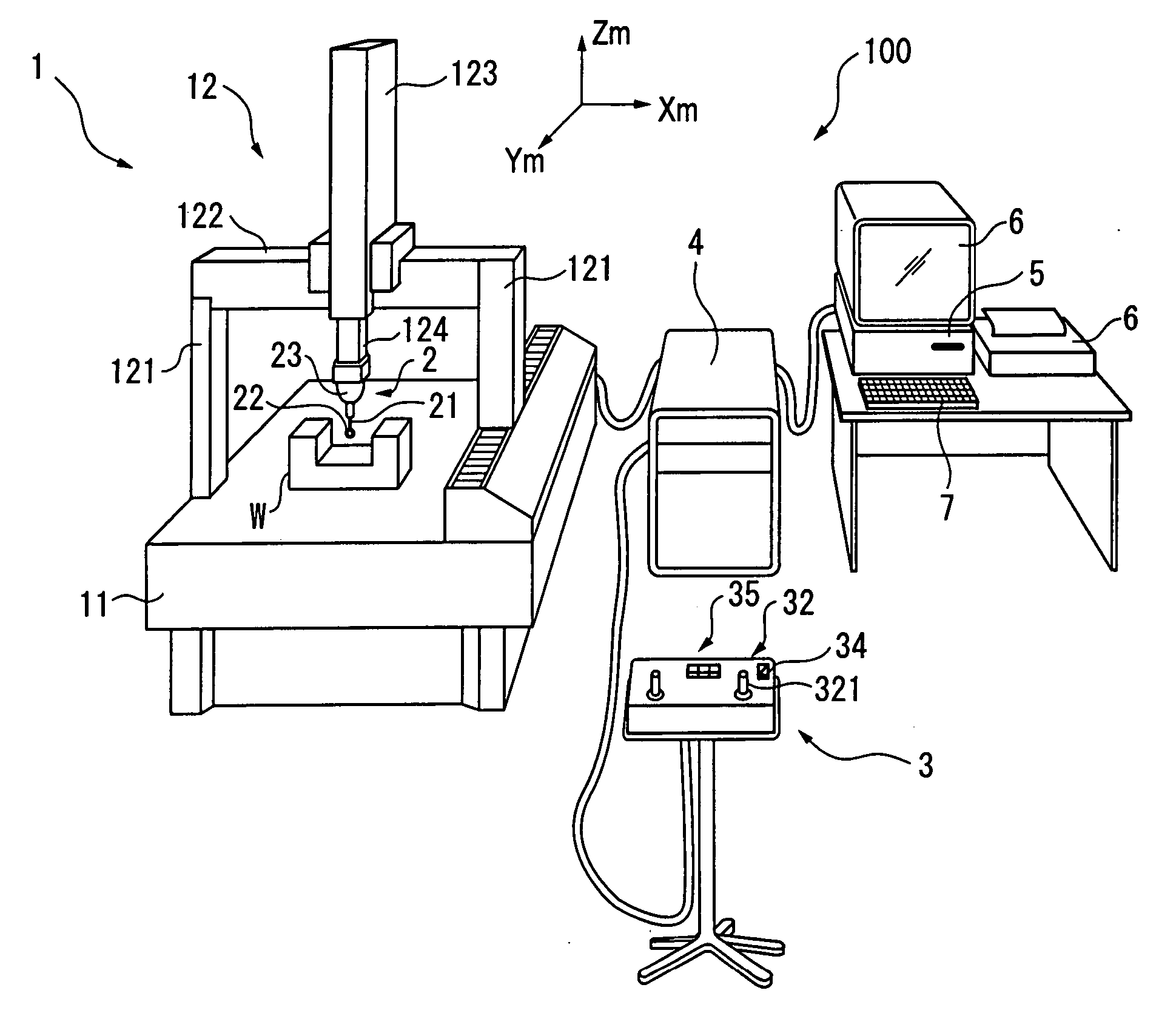
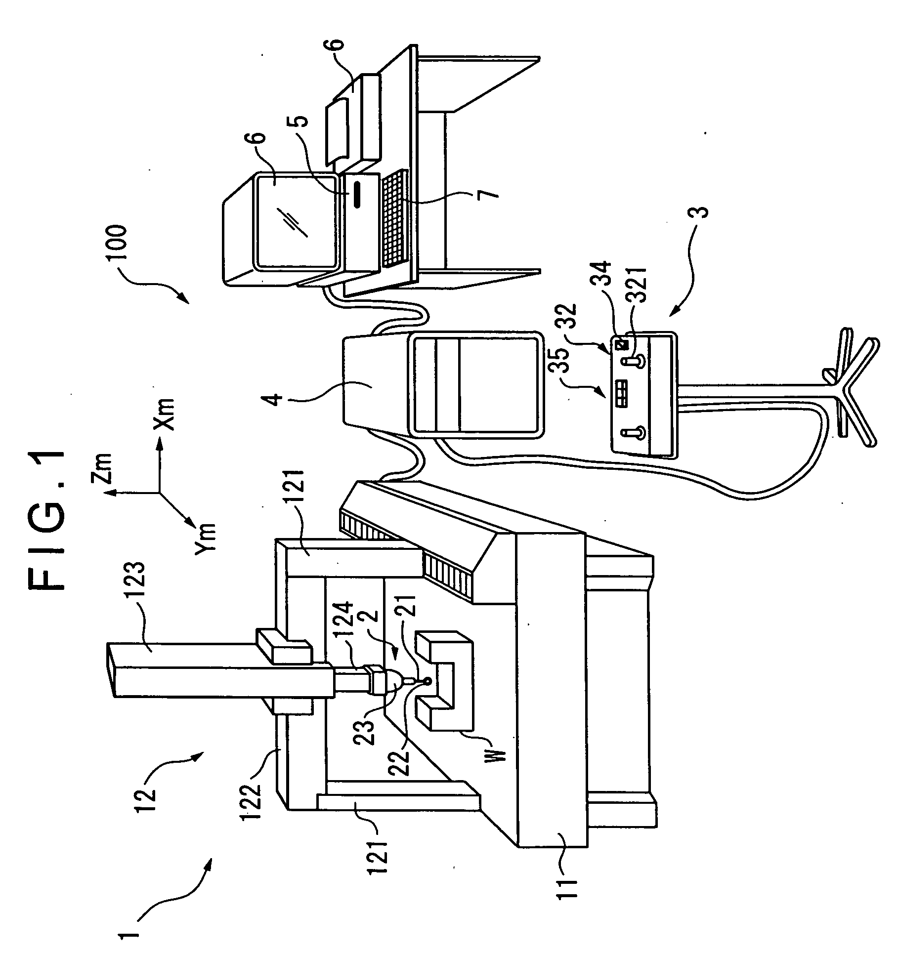
[0116]FIG. 1 is a schematic illustration of the first embodiment of the present invention, which is a measuring system including a coordinate measuring machine, showing the overall configuration thereof.

[0117] The measuring system 100 includes a coordinate measuring machine 1, an operating section 3 for manually operating the coordinate measuring machine 1, a motion controller 4 for driving and controlling the coordinate measuring machine 1 and a host computer 5 for issuing predetermined commands to the motion controller 4 and executing arithmetic processing operations such as form analysis of the workpiece W, an input section 7 for inputting the measuring conditions and an output section 6 for outputting the results of measurement.

[0118] The coordinate measuring machine 1 includes a surface plate 11, a drive mechanism (moving section) 12 standing on the surface plate 11 to drive a scanning probe 2 to move three-dimensionally, a drive sensor 13 ...

second embodiment

[0235] Now, the second embodiment of surface scan measuring device and that of surface scan measuring method will be described below.

[0236] The second embodiment is identical with the first embodiment in terms of the basic configuration thereof. However, the second embodiment is characterized in that it is adapted to trajectory scanning.

[0237]FIG. 17 shows a functional block diagram of the second embodiment.

[0238] Referring to FIG. 17, the host computer 5 includes a trajectory generating section 58 and the measurement condition storage section 55 receives form data of the workpiece W as input. The host computer 5 also includes an error judging section 51, which error judging section 51 by turn includes a mode shift commanding section 512.

[0239] The motion controller 4 includes a scanning vector commanding section 44, which scanning vector commanding section 44 by turn includes a trajectory scanning vector generating section 447 as shown in FIG. 18.

[0240] The form data that are ...

third embodiment

[0256] Now, the third embodiment of the present invention will be described below.

[0257] The third embodiment has a configuration that is basically the same as that of the second embodiment. However, the third embodiment differs from the second embodiment in that the trajectory generating section thereof includes a trajectory modifying section.

[0258]FIG. 22 is a functional block diagram of the third embodiment of the present invention. Referring to FIG. 22, the motion controller 4 includes a scanning vector commanding section 44, which scanning vector commanding section 44 by turn includes a trajectory scanning vector generating section 447 but does not include an autonomous scanning vector generating section. The error judging section (relative position determining section) 51 and the trajectory generating section 58 of the host computer 5 respectively include a trajectory modification commanding section (measurement mode switching section) 513 and a trajectory modifying section ...


PUM


Abstract

A surface scan measuring device, a surface scan measuring method, a surface scan measuring program and a recording medium storing such a program which can appropriately adjust the scanning speed, the sampling pitch and other measurement parameters according to the surface condition of a workpiece are provided. The surface scan measuring device includes a radius of curvature computing section (543) for computing the radius of curvature of the scanning point from the measurement data acquired during the ongoing scanning operation, a moving speed deciding section (544) for deciding the moving speed of the scanning probe according to the computed radius of curvature and a sampling pitch deciding section (546) for deciding the sampling pitch according to the computed radius of curvature.

Description

BACKGROUND OF THE INVENTION [0001] 1. Field of the Invention [0002] The present invention relates to a surface scan measuring device, a surface scan measuring method, a surface scan measuring program, and a recording medium. More specifically, the present invention relates to, for example, a surface scan measuring device for measuring the form of the surface of a workpiece along with the roughness, the waviness, the contour and other surface texture of the workpiece, [0003] 2. Description of Related Art [0004] Conventionally, a roughness measuring machine, a contour measuring machine, a roundness measuring machine, a coordinate measuring machine and the like are known as a measuring machine for measuring the surface texture and the three-dimensional profile of a workpiece by scanning the surface of the workpiece with a scanning probe (see, for example, Patent Document 1: Japanese Patent Application Laid-Open No. Hei. 5-248852, Patent Document 2: Japanese Patent Laid-Open Publication...

Claims


Application Information

Patent Timeline
IPC IPC(8): G01B5/008G01B5/20G01B21/00G01B21/04G01B21/20G05B19/19
CPCG01B5/008G01B5/20G05B2219/43124G05B2219/37359G05B2219/37402G01B21/045
Inventor NODA, TAKASHI
Owner MITUTOYO CORP
Learn More