
Implant surface preparation

a technology for implants and surfaces, applied in the field of implants, can solve the problems of less certainty about the ideal physical properties of the surfaces of prosthetic devices which confront the host bone, and the optimum surface for long-term stability has not yet been defined, so as to achieve uniform surface texture or roughness, uniform surface, and uniform surface topography

Inactive Publication Date: 2005-12-01
BIOMET 3I LLC
View PDF8 Cites 18 Cited by
  • Summary
  • Abstract
  • Description
  • Claims
  • Application Information

AI Technical Summary

Benefits of technology

[0011] It is a primary object of the present invention to produce an implant surface having a roughness that is substantially uniform over the area of the implant that is intended to bond to the bone in which the implant is placed.
[0014] It is an additional object of the invention to provide such improved implant devices which can be manufactured without contaminating the surfaces thereof.
[0015] It is a more specific object of the invention to provide an improved etch-solution process that will result in a substantially uniform surface topography on surgically implantable devices.
[0016] In accordance with the present invention, the foregoing objectives are realized by removing the native oxide layer from the surface of a titanium implant to provide a surface that can be further treated to produce a substantially uniform surface texture or roughness, and then performing a further, and different, treatment of the resulting surface substantially in the absence of unreacted oxygen. The removal of the native oxide layer may be effected by any desired technique, but is preferably effected by immersing the implant in hydrofluoric acid under conditions which remove the native oxide quickly while maintaining a substantially uniform surface on the implant. The further treatment is different from the treatment used to remove the native oxide layer and produces a desired uniform surface texture, preferably acid etching the surface remaining after removal of the native oxide layer. To enhance the bonding of the implant to the bone in which it is implanted, a bone-growth-enhancing material, such as bone minerals, hydroxyapatite, whitlockite, or bone morphogenic proteins, may be deposited on the treated surface. The implant is preferably maintained in an oxygen-free environment following removal of the native oxide layer, in order to minimize the opportunity for oxide to re-form before the subsequent treatment is performed.

Problems solved by technology

Surgical procedures for preparing living bone to receive a surgically implanted prosthetic device have been known for twenty years or more, but considerable controversy remains concerning the ideal properties of the surface of the device which confronts the host bone.
There is, however, less certainty about the ideal physical properties of the surfaces of the prosthetic devices which confront the host bone.
It appears that such cells will attach more readily to rough surfaces than to smooth surfaces, but an optimum surface for long-term stability has not yet been defined.

Method used


Image

  • Implant surface preparation
  • Implant surface preparation
  • Implant surface preparation

Examples


example 1

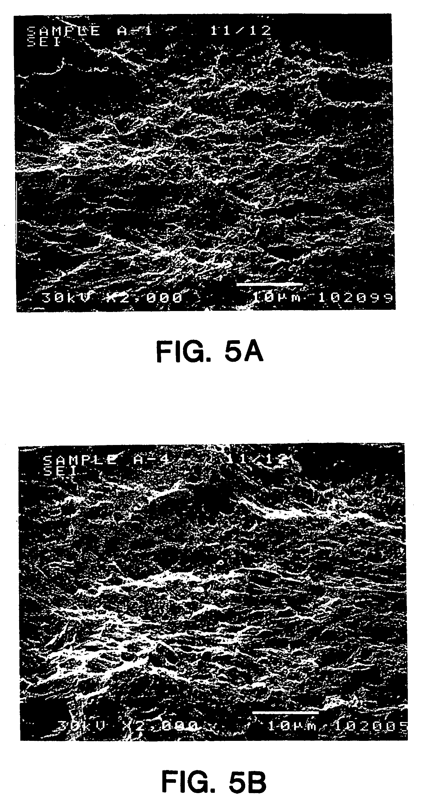
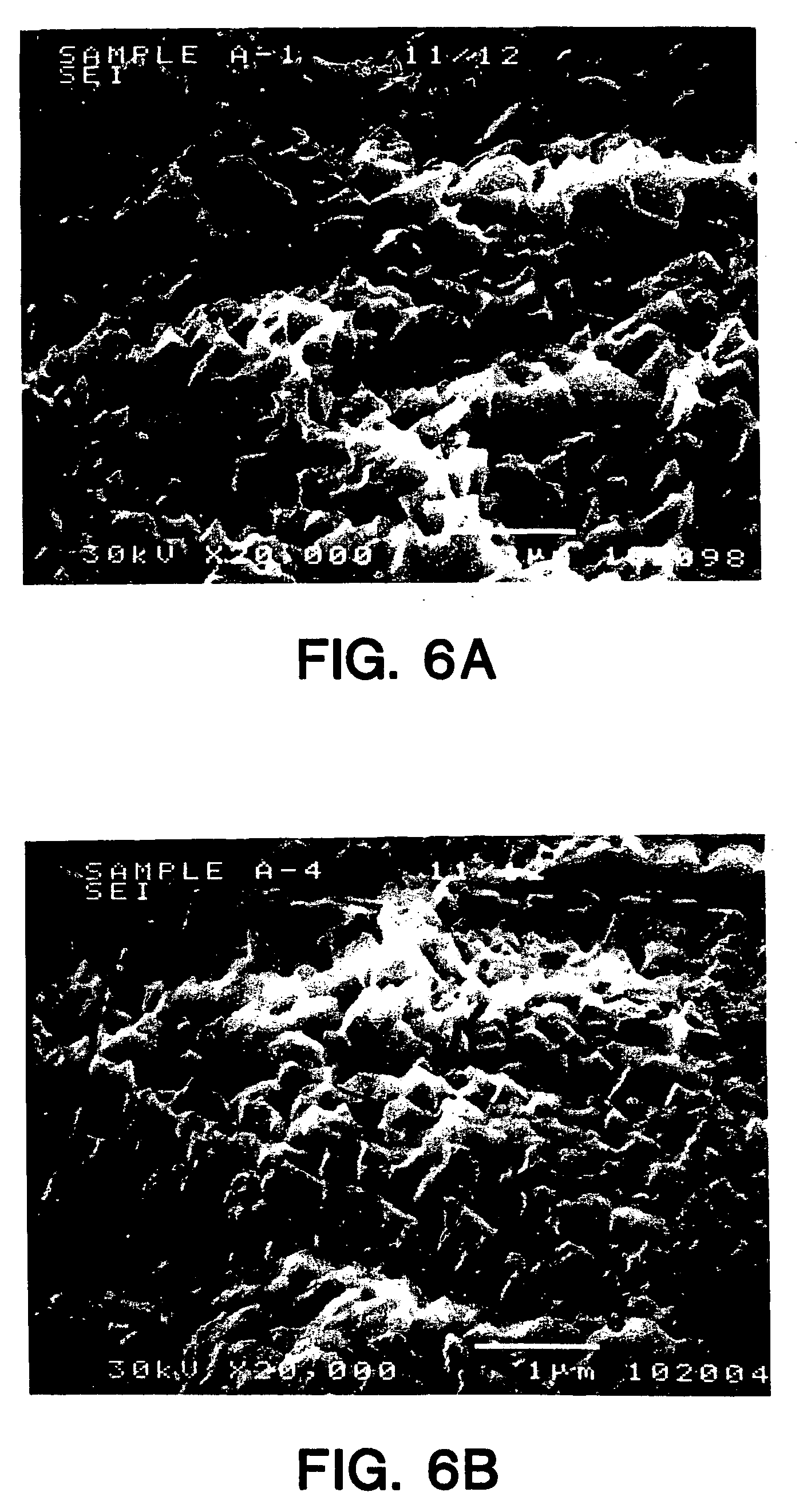
[0047] A batch of 30 screw-type cylindrical implants made of CP titanium were grit blasted using particles of CP B299 SL grade titanium grit having particle sizes ranging from 10 to 45 microns, at a pressure of 60 to 80 psi. After grit-blasting, native oxide layer was removed from the implant surfaces by placing 4 implants in 100 ml. of a 15% solution of HF in water at room temperature for 30 seconds. The implants were then removed from the acid, neutralized in a solution of baking soda, and placed in 150 ml. of “Modified Muriaticetch” (described above) at room temperature for 3 minutes. The implants were then removed from the acid, neutralized, rinsed and cleaned. All samples displayed very similar surface topographies and a high level of etch uniformity over the surface, when compared with each other in SEM evaluations. Consistency in the surface features (peaks and valleys) was also observed. The SEMs in FIGS. 5A, 5B, 6A and 6B show the surfaces of two of the implants, Sample A-1...

example 2

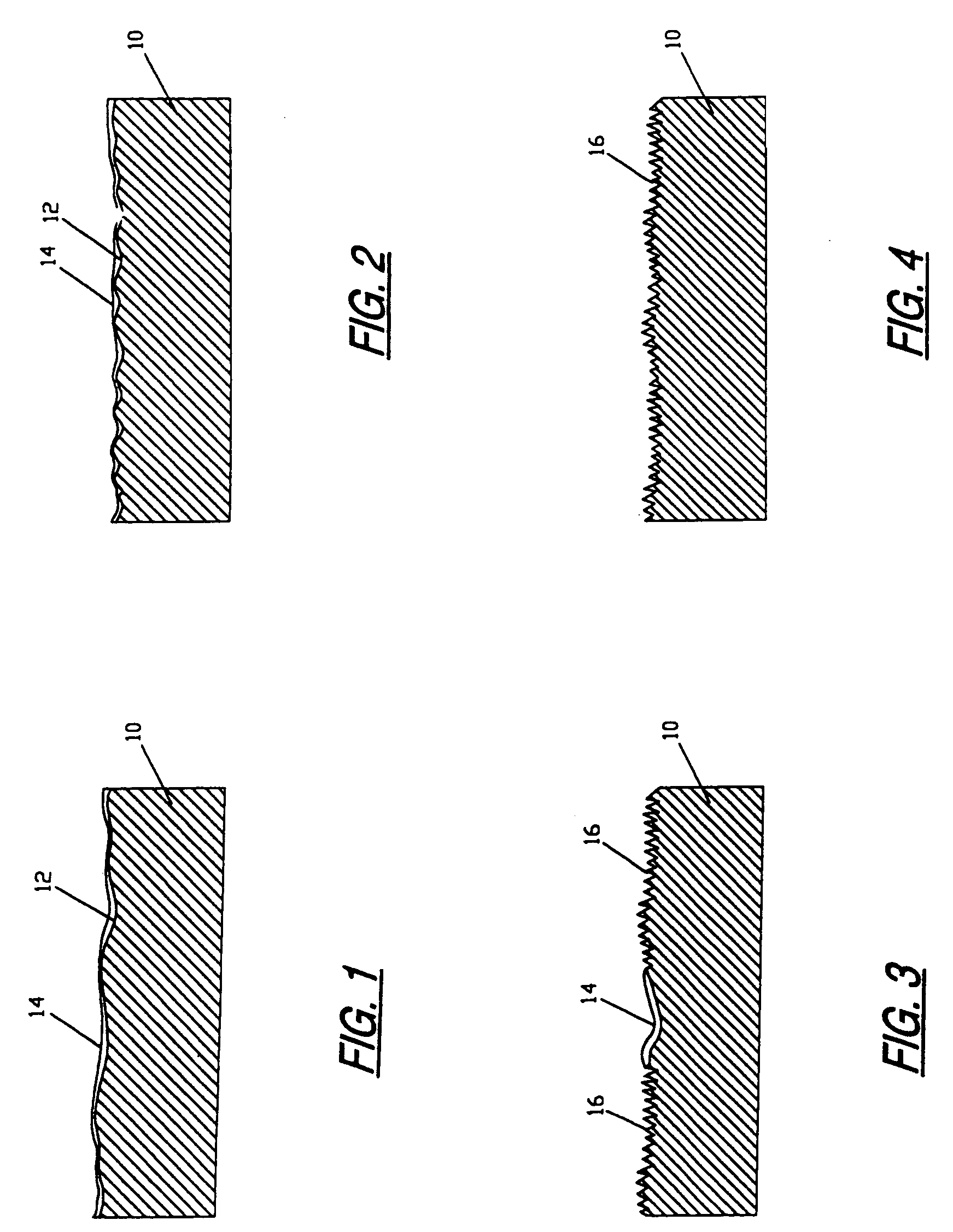
[0050] Four of the implants that had been grit blasted as described in EXAMPLE NO. 1 above were placed in 150 ml. of “Modified Muriaticetch” for 10 minutes. The implants were then removed, neutralized, rinsed and cleaned. SEM photographs taken at magnifications of 2,000 and 20,000 showed that the bulk etch solution failed to remove the native oxide layer after 10 minutes in the etch solution. The failure to remove the native oxide layer (100-150 Angstrom units thick) resulted in a non-uniformly etched surface, as depicted in FIG. 3. In areas of the implant surfaces where the native oxide was removed, the topography was similar to that observed on the implants in EXAMPLE NO. 1.

example 3

[0051] The procedure of this example is currently preferred for producing commercial implants. A batch of screw-type implants made of CP titanium were immersed in a 15% solution of HF in water at room temperature for 60 seconds to remove the native oxide layer from the implant surfaces. A plastic cap was placed over the top of each implant to protect it from the acid. The implants were then removed from the acid and rinsed in a baking soda solution for 30 seconds with gentle agitation. The implants were then placed in a second solution of baking soda for 30 seconds, again with agitation of the solution; and then the implants were rinsed in deionized water. Next the implants were immersed in another solution of two parts by volume sulfuric acid (96% by weight H2S04, 4% by weight water) and one part by volume hydrochloric acid (37% by weight HCl, 63% by weight water) at 70° C. for 5 minutes. The implants were then removed from the acid and rinsed and neutralized by repeating the same ...


PUM

PropertyMeasurementUnit
peak-to-valley heightsaaaaaaaaaa
contact angleaaaaaaaaaa
thicknessaaaaaaaaaa

Abstract

The surface of a device that is surgically implantable in living bone is prepared. The device is made of titanium with a native oxide layer on the surface. The method of preparation comprises the steps of removing the native oxide layer from the surface of the device and performing further treatment of the surface substantially in the absence of unreacted oxygen.

Description

CROSS REFERENCE TO RELATED APPLICATION [0001] This application is a continuation-in-part of pending U.S. patent application Ser. No. 08 / 351,214, filed Nov. 30, 1994, for “Implant Surface Preparation.”FIELD OF THE INVENTION [0002] The present invention relates to processes for improving the surfaces of devices to be surgically implanted in living bone, and to implant devices having the improved surfaces. BACKGROUND OF THE INVENTION [0003] The success of prosthetic devices surgically implanted in living bone depends substantially entirely on achieving and maintaining an enduring bond between the confronting surfaces of the device and the host bone. Surgical procedures for preparing living bone to receive a surgically implanted prosthetic device have been known for twenty years or more, but considerable controversy remains concerning the ideal properties of the surface of the device which confronts the host bone. [0004] It is known through clinical experience extending over several dec...

Claims


Application Information

Patent Timeline
Patent Type & Authority Applications(United States)
IPC IPC(8): A61C8/00A61F2/00A61F2/30A61L27/06A61L27/28A61L27/30A61L27/32A61L27/50B24C11/00B44C1/22
CPCA61C8/00C23F1/26A61C8/0013A61C8/0022A61C2008/0046A61F2/30767A61F2/30771A61F2/3094A61F2002/30838A61F2002/30904A61F2002/30906A61F2002/30925A61F2310/00023A61F2310/00616A61F2310/00796A61F2310/0097A61F2310/00976A61L27/06A61L27/28A61L27/306A61L27/32A61L27/50A61L2400/18A61L2430/02A61L2430/12B24C11/00A61C8/0012
Inventor BEATY, KEITH D.
Owner BIOMET 3I LLC
Learn More