


Quick Research
Generate reliable direction feasibility study reports for your R&D in just a few steps.

Technical Q&A
Discover and master advanced knowledge NOW. Basics, ideas, possibilities, all at once.

Find Solutions
As an expert in R&D theories, this can generate solutions to your technical problems instantly.

Evaluate Feasibility
Analyze your overall solution with one click, know your potential R&D risks in advance.

Monitor Landscape
Get weekly tech updates, stay abreast of the latest tech innovations and key insights.
Laitance removing device suitable for semi-flexible pavement
A semi-flexible pavement and cleaning device technology, applied in roads, roads, road repairs, etc., can solve the problems of large differences in road surface roughness, low processing efficiency, environmental pollution, etc., and achieve uniform roughness, good surface appearance, and High cleaning efficiency
- Summary
- Abstract
- Description
- Claims
- Application Information
AI Technical Summary
Problems solved by technology
Method used
Image

Examples
example 1
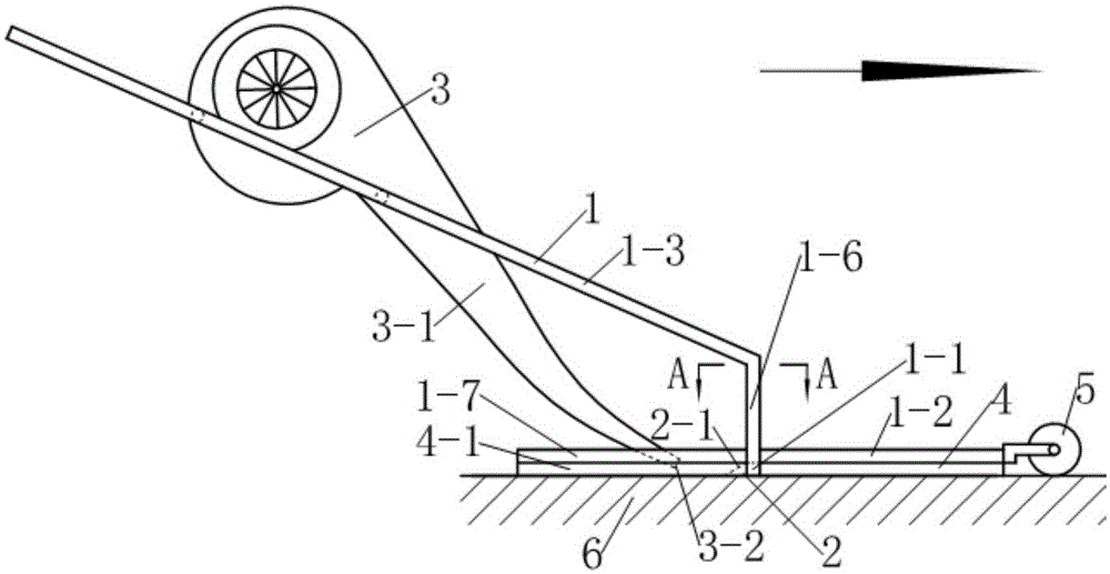
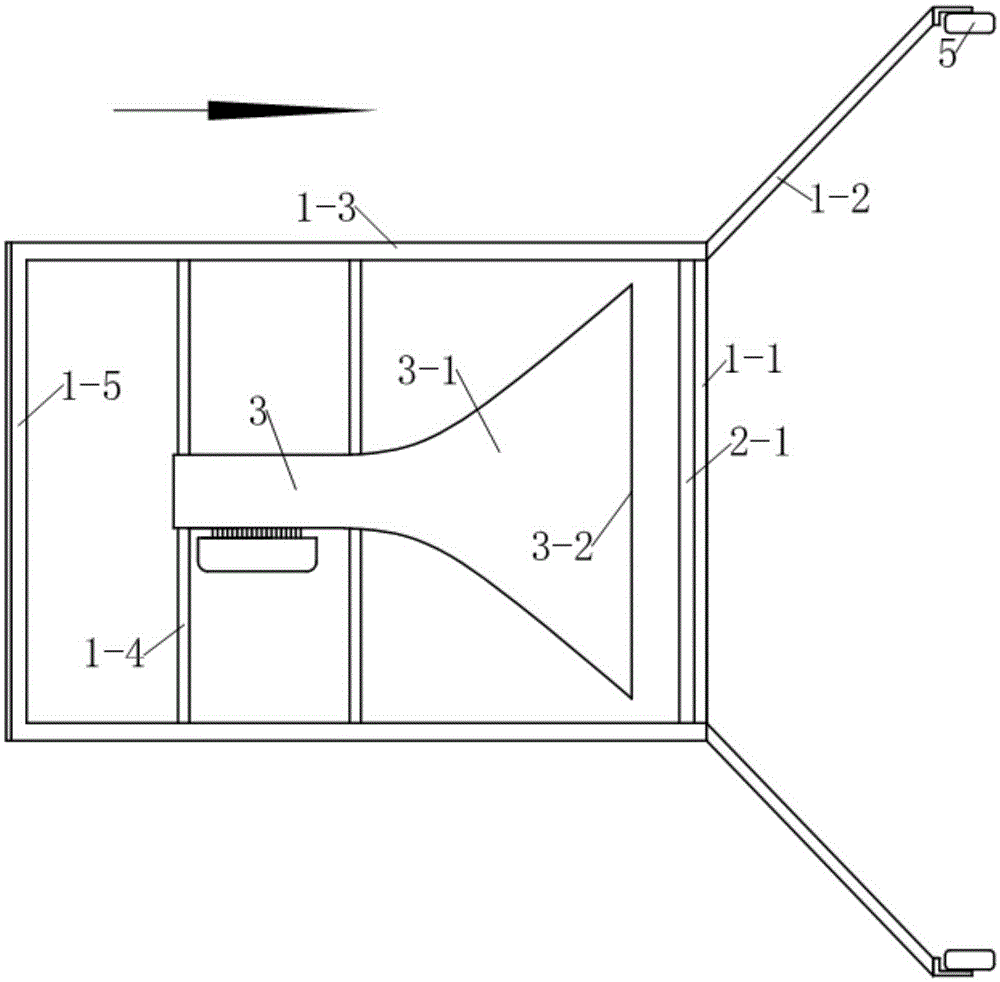
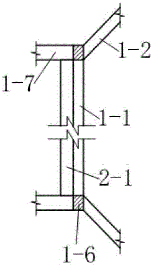
[0018] see Figure 1~4 , the laitance cleaning device in this example includes a frame 1, and the laitance scraper 2 and blower 3 are arranged on the frame 1 from front to back;
[0019] see Figure 1~4 , the frame 1 includes a rectangular frame 1-3 inclined to the rear and upward, the front ends of the two sides of the rectangular frame 1-3 vertically extend downwards a support rod 1-6, between the two support rods 1-6 A scraper beam 1-1 close to the ground 6 is provided. The scraper beam 1-1 is 2.5 cm high, 100 cm long, and has a rectangular cross section. The beam at the rear end of the rectangular frame 1-3 doubles as the handle 1-5 of the device. The lower heads of the two support rods 1-6 are respectively provided with a baffle beam 1-2 and an auxiliary baffle beam 1-7, and the two baffle beams 1-2 extend to the front of the rectangular frame 1-3 sides respectively, and are connected with the machine. The forward direction of the frame 1 is at an included angle of 45°, ...
example 2
[0024] Example 2 (this example is the experimental example of the effect of the floating slurry cleaning device in the verification example 1)
[0025] 1. Purpose of the experiment
[0026] Verify the use effect of the floating slurry cleaning device described in Example 1.
[0027] 2. Experimental method
[0028] Get two sections of road surface with a length of 50m respectively in the experimental road section with a width of 10m (two lanes including shoulders), one section is used as the experimental section, and the other section is used as the comparison section. The existing hydraulic flushing method cleans up the laitance. Record the construction time and labor quantity respectively.
[0029] After the maintenance of the two sections of pavement, several points were randomly selected on the pavement to investigate the structural depth.
[0030] 3 Experimental results
[0031] Table 1 Comparison results of apparent treatment effects
[0032]
[0033] Table 2 Com...
PUM
 Abstract
Description
Claims
Application Information
 - R&D Engineer
- R&D Manager
- IP Professional
- Industry Leading Data Capabilities
- Powerful AI technology
- Patent DNA Extraction
Browse by: Latest US Patents, China's latest patents, Technical Efficacy Thesaurus, Application Domain, Technology Topic, Popular Technical Reports.
© 2024 PatSnap. All rights reserved.Legal|Privacy policy|Modern Slavery Act Transparency Statement|Sitemap|About US| Contact US: help@patsnap.com