
Microchip - Yb fiber hybrid optical amplifier for micro-machining and marking

a hybrid optical amplifier and microchip technology, applied in the field of laser systems, can solve the problems of inability to obtain cleanly machined features with this machining technique, unacceptable collateral damage to the surrounding tissues, and inability to achieve heat transfer into the material for many applications, etc., to achieve short pulse duration, high efficiency, and high energy.

Inactive Publication Date: 2005-11-03
IMRA AMERICA
View PDF99 Cites 24 Cited by
  • Summary
  • Abstract
  • Description
  • Claims
  • Application Information

AI Technical Summary

Benefits of technology

[0019] According to the invention, the goals set out in the foregoing are achieved through the use of a miniature Q-switched pulse source which is coupled to a doped Yb fiber laser which obtains single mode amplification in a multi mode fiber. Short pulse duration, efficiency, high power, high energy, cost efficiency and compactness are essentially achieved through the use of the combination of a compact diode-pumped microchip laser and a specially designed diode-pumped fiber amplifier. Short duration is achieved through the short cavity length of a microchip laser, whereas high efficiency is achieved through the use of a Yb-doped fiber amplifier pumped at ˜980 nm. High power is achieved through cladding pumping geometry, and large fiber core (high core to cladding ratio).
[0020] High energy is achieved through a number of design features: the large core, with single mode excitation and propagation, allows a large cross-sectional area and, consequently, permits relatively low peak intensities and high saturation energies. Further, the large core provides a good core-to-cladding ratio, which in conjunction with the high doping level available for Yb significantly reduces the pump absorption length and allows for short amplifier lengths (0.1 to ˜2 m), thus reducing detrimental nonlinear effects in the fiber without compromising power and energy extraction efficiencies. For very large cores, direct in-core pumping can be used. Side pumping provides higher power extraction efficiency and shorter interaction length compared to copropagating geometries (along with pump diode protection). Pigtailing of the fiber ends increases the surface damage threshold and allows a significant increase in output pulse energies and powers, while a composite core allows the robust coupling of the microchip seed pump into a fundamental mode of the fiber core. This also permits use of a non-perfectly-gaussian input beam from the microchip laser.

Problems solved by technology

Cleanly machined features cannot be obtained with this machining technique owing to the tendency of the molten material to spatter the workpiece and / or freeze and harden on the workpiece itself.
In the case of biological procedures, this heat transfer effect typically causes unacceptable collateral damage to the surrounding tissues.
However, even in the above mentioned pulse width range, the degree of heat transfer into the material is unacceptable for many applications.
At these ultrashort pulse widths, collateral damage to surrounding regions becomes almost negligible, because of the lack of significant heat transfer into zones outside of the immediate target area.
Thus, there is a need in the industrial and medical fields for a micro-machining or marking laser which reduces the collateral damage problems of the prior art, yet has a cost comparable to the present sources.
However, it is known that this shortening of the cavity length normally reduces the mode volume which makes if more difficult to achieve suitable pulse energies.
Further amplification in a solid-state amplifier is usually not a practical solution due to the very low gain characteristic of solid-state amplifiers.
Moreover, pushing the energies from a short pulse microchip laser sufficient for micromachining, reduces the microchip laser efficiencies to around 5%.
Known Nd: based lasers, in addition to being expensive, are less efficient compared to Yb-doped fiber amplifiers.
The amplification of high peak-power and high-energy pulses in a diffraction-limited optical beam in single-mode (SM) optical fiber amplifiers is generally limited by the small fiber core size that needs to be employed to ensure SM operation of the fiber.
In the early work in this area (Kafka and Snitzer) only double-clad fiber amplifiers comprising a SM core were considered for cladding-pumping, resulting in obvious limitations for the amplification of high peak power pulses.
The work by Kafka was equally restrictive in that it only considered double-clad fibers with a single-mode core pumped with coherent pump diode lasers.
However, none of the work by Goldberg and DiGiovanni (or Kafka, Snitzer or Waarts et al.) considered any technique for the effective use of multi-mode double-clad fibers as diffraction-limited or near diffraction-limited high-power amplifiers.
Moreover, the specific pump injection technique suggested by DiGiovanni comprises built-in limitations for the efficiency of fundamental-mode excitation in multi-mode fiber amplifiers.
Due to the limited packing ability of circular structures, air gaps remain in the fiber bundle before tapering.
Hence the central core region and the fundamental mode also become distorted which limits the excitation efficiency of the fundamental mode in a MM fiber when splicing the fiber bundle to the double-clad fiber.
In fact any geometric differences in the cladding shape of the fiber bundle or the double-clad fiber will lead to a limited excitation efficiency of the fundamental mode in the MM fiber in the process of splicing.
However, for multimode fiber, elliptical core fiber is the easiest to manufacture and to obtain at this time.

Method used


Image

  • Microchip - Yb fiber hybrid optical amplifier for micro-machining and marking
  • Microchip - Yb fiber hybrid optical amplifier for micro-machining and marking
  • Microchip - Yb fiber hybrid optical amplifier for micro-machining and marking

Examples


Embodiment Construction

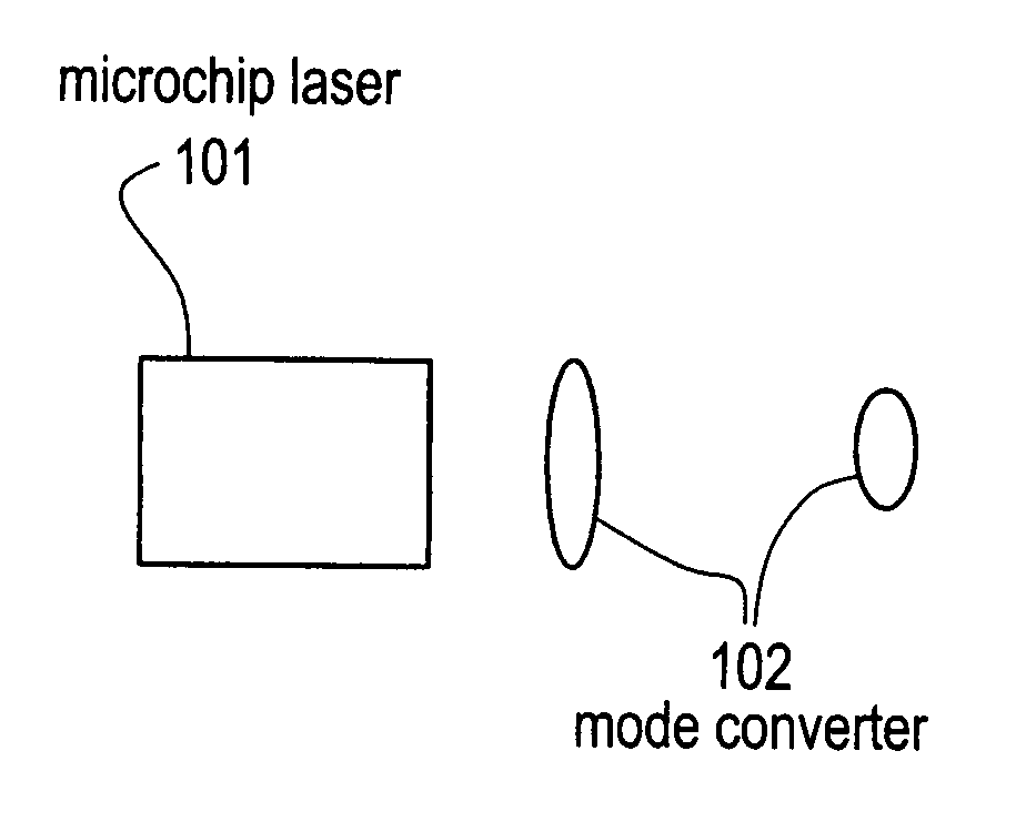
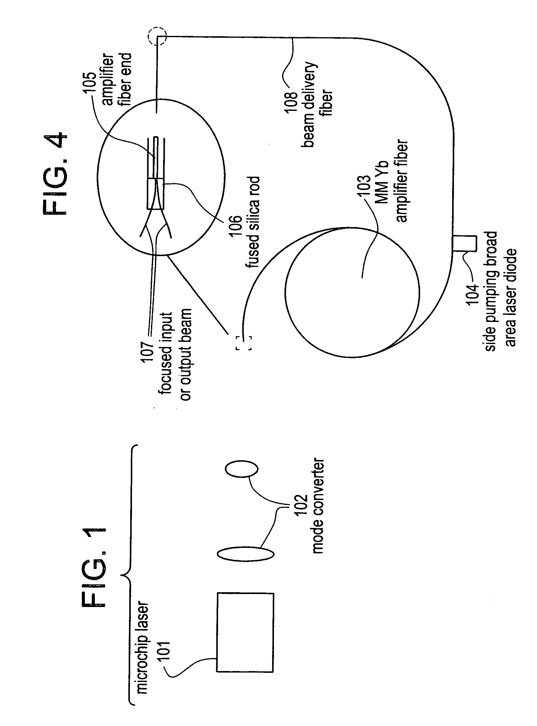
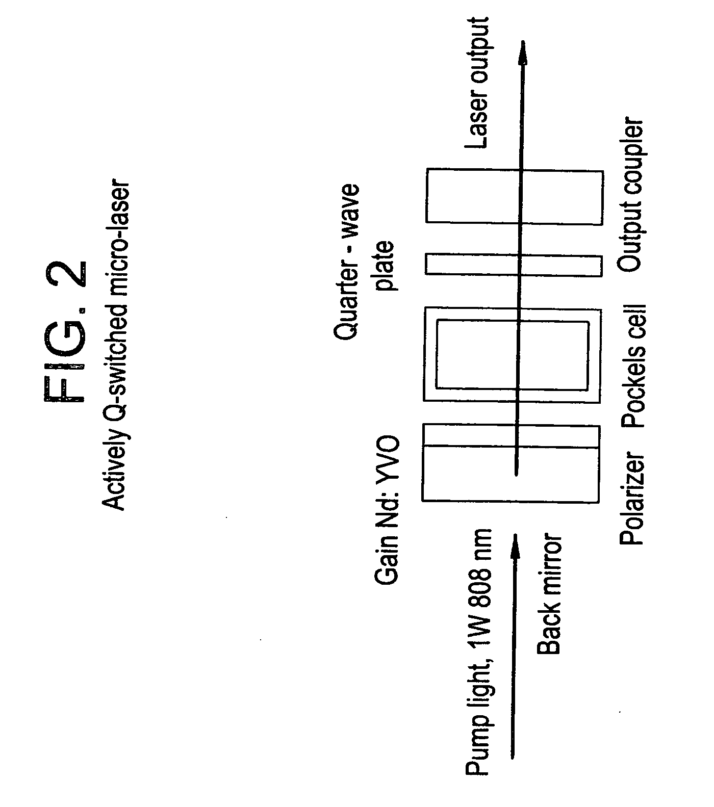
[0026]FIG. 1 illustrates the system configuration of the laser according to the present invention. In this Figure, reference numeral 101 indicates a microchip laser source, illustrated in greater detail in FIGS. 2 and 2(a). It should be noted that, as used herein, the term “micro chip laser” refers to a laser of small device size, where at least some of the components, such as the gain medium and the end mirror, are monolithic. In this specification, the terms “microchip laser” and “microlaser” are used interchangeably to refer to a laser having these characteristics. As described in detail below, the micro chip laser 101 according to the invention is an actively Q-switched laser which is typically diode pumped.

[0027] In order to achieve excitation of only the fundamental mode in a multimode-core fiber amplifier, the beam waist ωinput of a mode coupled into the amplifier from a microchip laser has to approximately match the beam waist ωmode of this fundamental mode: ωinput≈ωmode. N...


PUM


Abstract

The invention describes techniques for the control of the spatial as well as spectral beam quality of multi-mode fiber amplification of high peak power pulses as well as using such a configuration to replace the present diode-pumped, Neodynium based sources. Perfect spatial beam-quality can be ensured by exciting the fundamental mode in the multi-mode fibers with appropriate mode-matching optics and techniques. The loss of spatial beam-quality in the multi-mode fibers along the fiber length can be minimized by using multi-mode fibers with large cladding diameters. Near diffraction-limited coherent multi-mode amplifiers can be conveniently cladding pumped, allowing for the generation of high average power. Moreover, the polarization state in the multi-mode fiber amplifiers can be preserved by implementing multi-mode fibers with stress producing regions or elliptical fiber cores These lasers find application as a general replacement of Nd: based lasers, especially Nd:YAG lasers. Particularly utility is disclosed for applications in the marking, micro-machining and drilling areas.

Description

[0001] This application is a continuation-in-part of pending application Ser. No. 09 / 116,241, filed Jul. 16, 1998.FIELD OF THE INVENTION [0002] This invention relates generally to laser systems having application to such fields as micro-machining, drilling and marking. A primary characteristic of these lasers is their high-powered short-pulsed output, which in, for example, an industrial application, preferably machines the surface of a target or workpiece by an ablation technique. The invention also relates generally to laser systems which can serve in replacement of more expensive Nd based lasers, such as diode-pumped Q-switched Nd:YAG lasers and other lasers using Nd-based materials. BACKGROUND OF THE INVENTION [0003] It has been known in the prior art to use pulsed laser systems to effect such processes as diverse as metal machining and biological tissue removal. Of chief concern in these systems is the amount of “collateral damage” to the surrounding regions of the workpiece, o...

Claims


Application Information

Patent Timeline
IPC IPC(8): H01S3/06H01S3/067H01S3/094H01S3/10H01S3/11H01S3/16H01S3/30
CPCG02B6/262H01S3/302H01S3/0606H01S3/0615H01S3/0627H01S3/06708H01S3/06754H01S3/094003H01S3/094007H01S3/094069H01S3/09415H01S3/115H01S3/1611H01S3/1618H01S3/1673G02F1/3525
Inventor HARTER, DONALD J.FERMANN, MARTIN E.
Owner IMRA AMERICA
Learn More