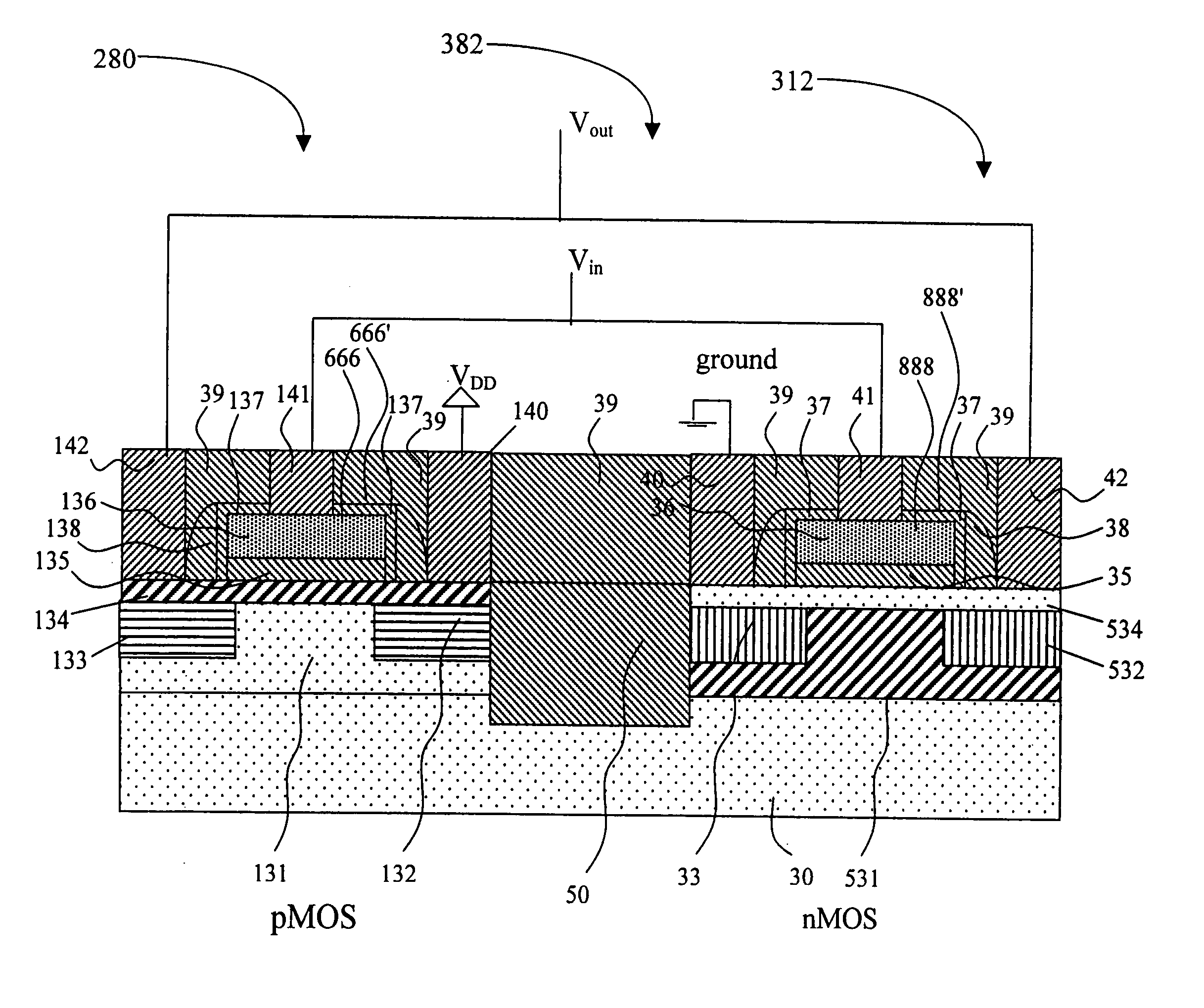
High speed lateral heterojunction MISFETS realized by 2-dimensional bandgap engineering and methods thereof
a technology of lateral heterojunction and misfets, applied in the field of metal insulator semiconductor field effect transistors, can solve the problems of difficult to achieve abrupt doping profiles, traditional techniques that fail to reduce certain undesirable physical effects, and the scaling of silicon mosfets has become a major challenge, so as to achieve superb performance and scalability, optimize drive current and leakage current, and avoid tradeoffs in conventional si technology.
- Summary
- Abstract
- Description
- Claims
- Application Information
AI Technical Summary
Benefits of technology
Problems solved by technology
Method used
Image
Examples
first embodiment
[0024] The cross sectional schematic for a SiGe based lateral nMOSFET 78 is shown in FIG. 4. The device has the following structural characteristics: [0025] 1) The drain is n+-type tensile strained silicon 82; [0026] 2) The body is p-type relaxed SiGe 81, and the doping level is adjusted to achieve desirable the threshold voltage; [0027] 3) The source is n+-type tensile strained silicon 83; [0028] 4) The channel is tensile strained Si 84, and there is no hetero-barrier along the current flow direction shown by arrow 93. The channel forms a heterojunction with the body 81 at the interface 805 which functions to provide a band offset as shown in FIG. 3 to confine electrons in the Si channel 84. The channel is typically autodoped by the layer below. Thus the channel region over the body 81 is autodped p-type, while the channel region over the source 83 and drain 82 are doped n-type. There are other ways to provide the desired doping in the channel layer and source / drain. [0029] 5) A st...
second embodiment
[0037] Besides using a relaxed SiGe as the virtual substrate to generate a tensile strained Si layer, tensile strained SiC on silicon can also be used for nMOSFET. The cross sectional schematic for such a silicon-based lateral nMOSFET 112 is shown in FIG. 5. The device has the following structural characteristics: [0038] 1) The drain is n+-type tensile strained SiC 32; [0039] 2) The body is p-type silicon 31, and the doping level is adjusted to achieve the desirable threshold voltage; [0040] 3) The source is n+-type tensile strained SiC 33; [0041] 4) The channel is silicon or tensile strained SiC 34, and there is no hetero-barrier along the current flow direction; [0042] 5) A strained SiC / Si heterojunction is formed between the source and the body at the interface 820, and is preferably, aligned with the source / body metallurgical p / n junction; [0043] 6) A strained SiC / Si heterojunction is formed between the drain and the body at the interface 830, and is preferably, aligned with the...
PUM
| Property | Measurement | Unit |
|---|---|---|
| concentration | aaaaa | aaaaa |
| permittivity | aaaaa | aaaaa |
| conducting | aaaaa | aaaaa |
Abstract
Description
Claims
Application Information
 - R&D
- Intellectual Property
- Life Sciences
- Materials
- Tech Scout
- Unparalleled Data Quality
- Higher Quality Content
- 60% Fewer Hallucinations
Browse by: Latest US Patents, China's latest patents, Technical Efficacy Thesaurus, Application Domain, Technology Topic, Popular Technical Reports.
© 2025 PatSnap. All rights reserved.Legal|Privacy policy|Modern Slavery Act Transparency Statement|Sitemap|About US| Contact US: help@patsnap.com


