Screw extruder and extruder screw for improved heat transfer

a technology of screw extruder and screw screw, which is applied in the direction of manufacturing tools, food shaping, sweetmeats, etc., can solve the problems of insufficient heat-transfer improvement, insufficient height and width, and inability to make significant improvement in heat-transfer, so as to improve mixing, improve heat-transfer effect, and improve the effect of heating the polymer mel

Inactive Publication Date: 2005-10-27
RAUWENDAAL EXTRUSION ENG
View PDF9 Cites 3 Cited by
  • Summary
  • Abstract
  • Description
  • Claims
  • Application Information

AI Technical Summary

Benefits of technology

[0033] An advantage of the present invention is that the extruder can provide improved heating of the polymer melt (or whatever material is being extruded).
[0034] Another advantage of the present invention is that the extruder can provide improved mixing, both cross sectional and longitudinal mixing.
[0035] And another advantage of the present invention is that the extruder can produce a narrower residence time distribution.
[0036] A further advantage of the present invention is that the extruder can provide higher throughput in the extrusion process.
[0037] A yet further advantage is that the extruder can reduce the product change-over time when changing form material A to B.
[0038] These and other objects and advantages of the present invention will become clear to those skilled in the art in view of the description of the best presently known mode of carrying out the invention and the industrial applicability of the preferred embodiment as described herein and as illustrated in the several figures of the drawings.

Problems solved by technology

The paper describing the “inside-out mixer” helps to improve back-mixing, but does not directly address the problems of heat-transfer.
In particular, a typical mixer is only 1-3 D long, which is insufficient to make significant improvement in heat-transfer.
In addition, for typical plasticating extruders the flight height is about 0.05 D-0.10 D and typical flight width in plasticating extruders is 0.10 D. These flight heights and widths do not allow for significant improvement in heat transfer.

Method used


Image

  • Screw extruder and extruder screw for improved heat transfer
  • Screw extruder and extruder screw for improved heat transfer
  • Screw extruder and extruder screw for improved heat transfer

Examples


Embodiment Construction

[0046] The present invention is an extruder screw improved for heat transfer or “high heat transfer (HHT) screw”, which is shown in FIGS. 4 and 5, and will be designated by the element number 10.

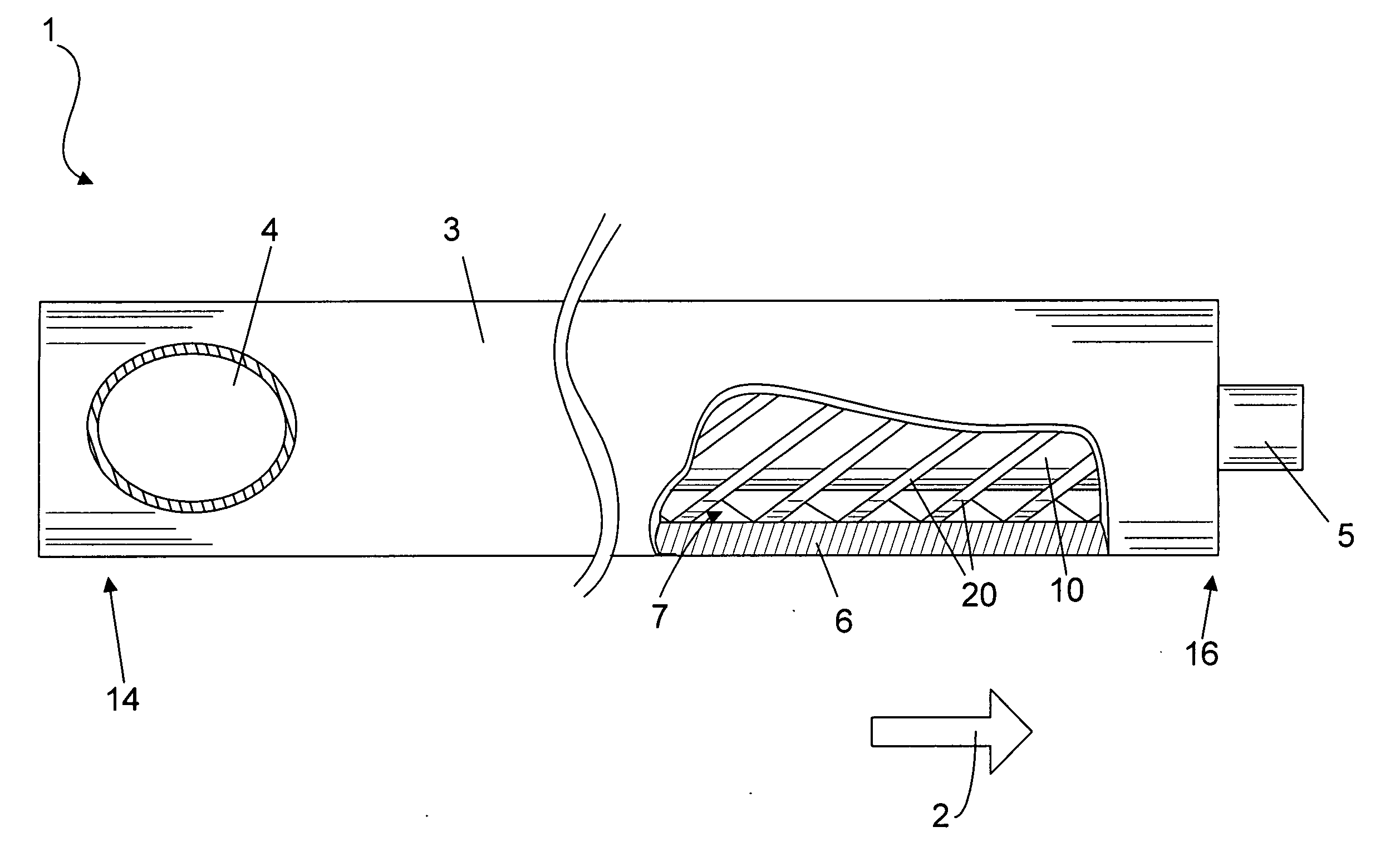
[0047]FIG. 4 shows the extruder screw 10 mounted in a screw extruder 1.

[0048] The screw extruder 1 has an input end 14 and an output end 16. Generally, for convenience of reference, the terms “downstream” shall refer to those ends closest to the output portion of the screw extruder and the term “upstream” shall refer to those ends farthest away from the output. The downstream direction is indicated by a large arrow 2, which shows the direction of material flow. The screw extruder 1 has a barrel 3. The input end 14 includes an input hopper 4 for feeding in material, and an extrusion die 5 on the output end 16. A portion of the barrel 3 has been cut away to show the barrel wall 6, and an inner bore 7. Positioned within the bore 7 is the extrusion screw 10 having screw flights 20. Although th...


PUM

PropertyMeasurementUnit
melt temperatureaaaaaaaaaa
barrel temperatureaaaaaaaaaa
inlet temperatureaaaaaaaaaa

Abstract

An extruder screw (10) for a screw extruder (1) is disclosed having a central shaft (18) and a number of screw flights (20) arranged upon the central shaft (18). At least one of the screw flights (20) includes at least one discontinuity (38) which is an interruption in the screw flight (20) by which a portion of said screw flight (38) is offset circumferentially from the remainder of the screw flight (38). Also disclosed is a screw extruder (1) including a screw (10) having at least one discontinuity (38), a method of cooling material in a screw extruder (1), and a method of extruding material from a screw extruder (1) while cooling material within the screw extruder (1).

Description

[0001] The present application claims priority from provisional application 60 / 565,091, filed Apr. 22, 2004 to the present inventor.TECHNICAL FIELD [0002] The present invention relates generally to screw extruders and machinery for fabrication of extruded parts. BACKGROUND ART [0003] Heat transfer is a critical issue in most polymer extrusion operations. In plasticating extrusion the objective is to add the right amount of heat to melt the polymer and to achieve the desired melt temperature. In some extrusion operations, however, the objective is to remove heat from the polymer. This is the case in tandem foam extrusion lines where the secondary extruder is used to cool down the mixture of polymer melt and blowing agent. Cooling extruders reduce the polymer melt temperature by a substantial amount, about 100° C., to achieve a melt consistency that is conducive for foaming [0004] As the foam extrusion industry faces pressure to move from CFC (chlorofluorocarbon) blowing agents to HCF...

Claims


Application Information

Patent Timeline
Patent Type & Authority Applications(United States)
IPC IPC(8): B29C48/395B29C48/605B29C48/85
CPCB29C47/0009B29C47/60B29C47/6075B29K2025/00B29K2105/04B29C47/84B29C48/03B29C48/834B29C48/84B29C48/85B29C48/605
Inventor RAUWENDAAL, CHRIS J.
Owner RAUWENDAAL EXTRUSION ENG
Why Eureka
Try Eureka