
Method and apparatus for quantification of optical properties of superficial volumes

Inactive Publication Date: 2005-10-13
RGT UNIV OF CALIFORNIA
View PDF9 Cites 36 Cited by
  • Summary
  • Abstract
  • Description
  • Claims
  • Application Information

AI Technical Summary

Benefits of technology

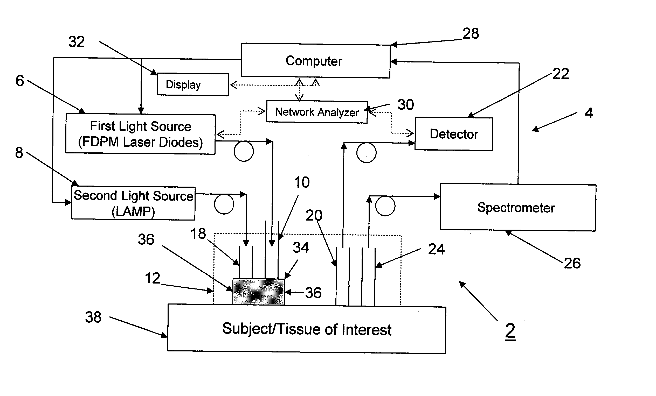
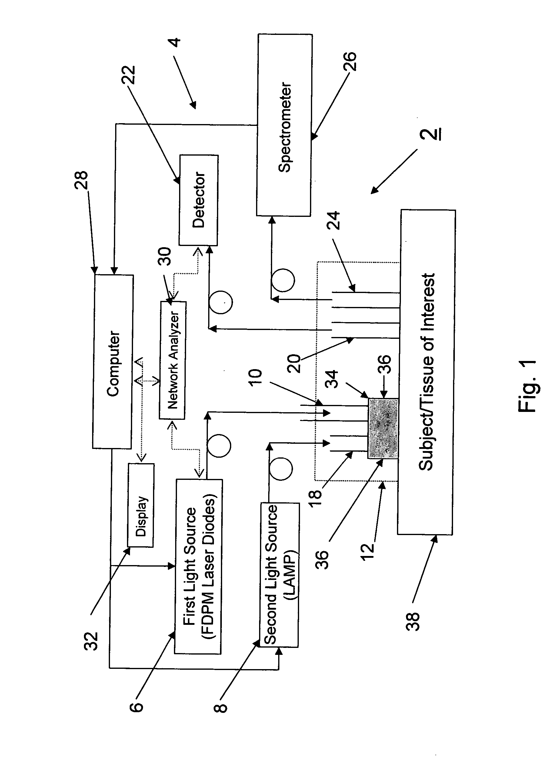
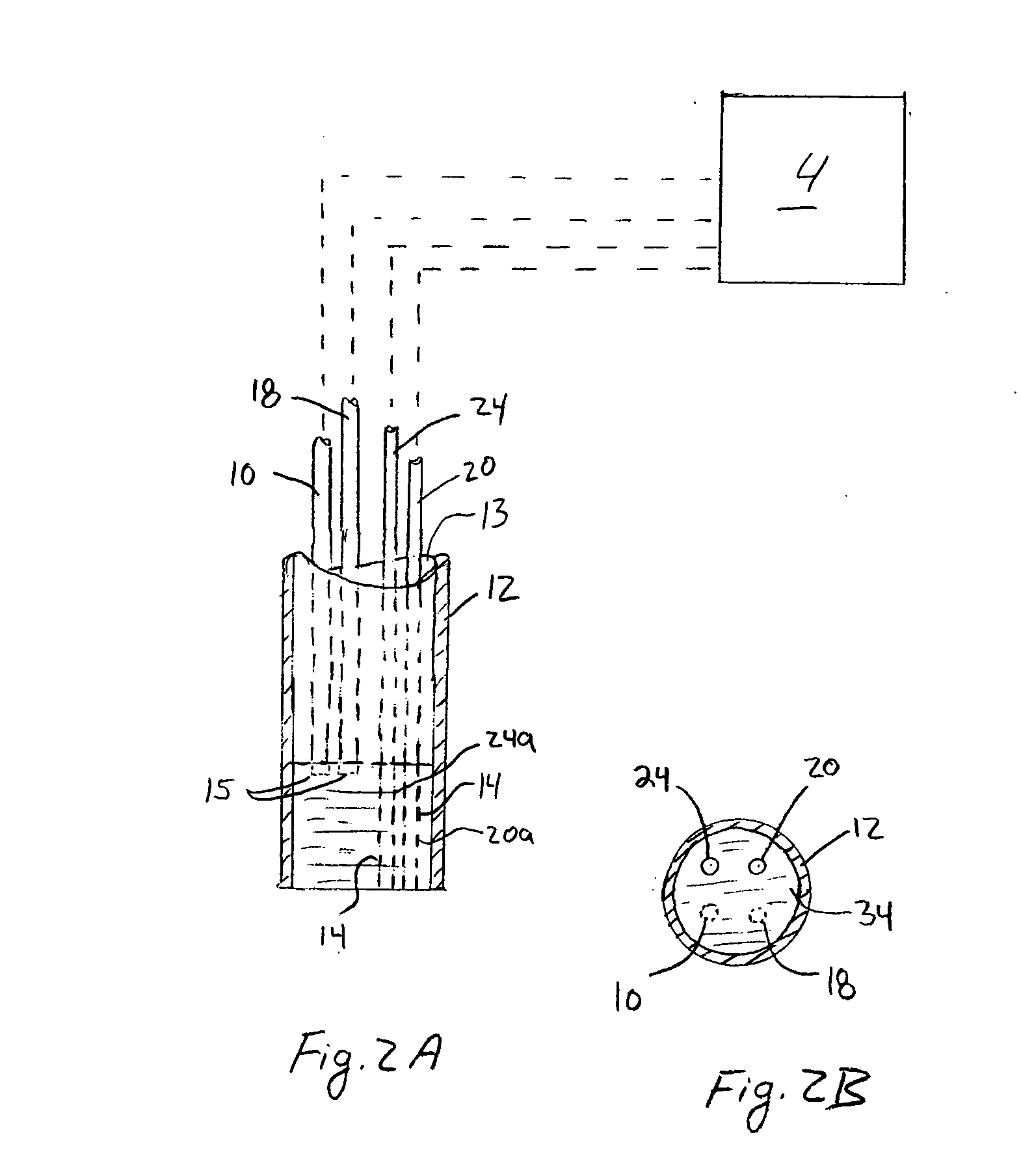
[0010] The present invention is directed to a method and device used to quantify the optical properties of biological or even non-biological material. The method and device described herein reduces the source-detector separation distance while at the same time maintains the validity of existing diffusion approximation techniques. The method and device uses a diffuser which is made of a high scattering, low absorption material. The diffuser is interposed between the surface of the sample and the distal end of the optical fiber coupled to the radiation source. The high scattering, low absorption material effectively increases the photon path length and allows the source-detector separation to be made arbitrarily small.

Problems solved by technology

Consequently, current diffuse optical spectroscopy methods are limited to situations in which the reduced scattering coefficient, μs′ is greater (by an order of magnitude) than the absorption coefficient, μa.
In each of these scenarios, however, a simple application of diffusion approximation-based modeling will yield inaccurate tissue optical properties and chromophore concentrations.
The disadvantage of a multi-fiber probe geometry is that each fiber samples a slightly different volume of tissue so there is inherent inaccuracy in the method.
The problem with this approach is that the calibration samples have to be very similar to the target (unknown) sample set of interest.

Method used


Image

  • Method and apparatus for quantification of optical properties of superficial volumes
  • Method and apparatus for quantification of optical properties of superficial volumes
  • Method and apparatus for quantification of optical properties of superficial volumes

Examples


experiment 1

[0079] A DOS system 2 utilizing a diffuser 34 (in the form of a layer) was used to demonstrate that the validity of the diffusion approximation is maintained even as the source-detector separation distance is reduced to a distance of 2.5 mm. Frequency domain measurements were made at several wavelengths to recover the optical properties of tissue phantoms, using a two-layer model for which the optical properties and thickness of the upper, highly scattering layer were known.

[0080] In this approach, a high scattering, low absorption diffuser 34 layer was interposed between the distal end of the source optical fiber 10 and the sample source layer 38 (μs′=9 mm−1 and μa=0.0015 mm−1 at 661 nm). The diffuser 34 layer effectively increased the photon path length and allowed the source-detector separation to be made arbitrarily small. The general operation of the multi-wavelength frequency-domain spectroscopy system 2 is described in F. Bevilacqua, A. J. Berger, A. E. Cerussi, D. Jakubowsk...

experiment 2

[0091] In a conventional DOS measurement in which the source optical fiber 10 and the detector optical fiber 20 are flush with sample 38 under investigation, a standard diffusion model is generally employed to recover sample's optical properties for its simplicity and efficiency. Unfortunately, the standard diffusion model is feasible only when the sample under investigation has μs′ / μa>10 and the source optical fiber 10 and detector optical fiber 20 separation distance is much larger than 1 / (μs′+μa). In some applications, for example, measuring skin melanin concentration using NIR light, samples 38 have μs′ on the same order of μa, and the standard diffusion equation typically used is not appropriate for recovering optical properties of such samples 38.

[0092] The modified two-layer (MTL) geometry described herein uses a diffuser 34 in the form of a very high scattering top layer to make light radiance isotropic in a very short distance (1-2 mm). By using the diffuser 34, a diffusio...

experiment 3

[0094] The optical properties (μs′, μa) of human skin were determined by using MTL-based DOS system 2. Measurements were made in vivo in a non-invasive manner. In this experiment, the optical properties of forearm skin of three healthy subjects were measured. The subjects were of African, Caucasian, and Asian descent. The optical properties (μs′, μa) were determined at four different wavelengths using the DOS system 2 described herein. FIGS. 13A and 13B illustrate the measured optical properties (μs′, μa) as a function of the different wavelengths for each subject. The measured μa of the forearm skin of the African subject is much higher than those of the other two subjects (around 500% higher at 660 nm). In contrast, the μs′ of the skin of the three subjects were generally close to one another (generally within 10% for most of wavelengths). It is believed that the μa differences in this wavelength range are mainly due to the differences in melanin concentration of three subjects. C...


PUM


Abstract

A device and method for accurately performing quantitative diffuse optical spectroscopy on a sample includes a light source and a source optical fiber that is optically coupled to the light source. A diffuser material is interposed between the source optical fiber and the sample, the diffuser material comprising a high scattering, low absorption material. The diffuser material effectively increases the photon path length from the light source to the sample, which limits the depth of interrogation to superficial volumes despite the penetrating nature of the radiation typically used. A detector optical fiber is provided adjacent to or laterally disposed from the source optical fiber. The detector optical fiber is coupled to a detector which detects photons collected in the detector optical fiber. The detector optical fiber and the source optical fiber may be separated by a distance of less than 5 mm while still permitting the diffusion approximation to remain valid.

Description

REFERENCE TO RELATED APPLICATIONS [0001] This Application claims priority to U.S. Provisional Patent Application No. 60 / 561,836 filed on Apr. 13, 2004. The '836 application is incorporated by reference as if set forth fully herein.STATEMENT REGARDING FEDERALLY SPONSORED RESEARCH AND DEVELOPMENT [0002] The U.S. Government may have a paid-up license in this invention and the right in limited circumstances to require the patent owner to license others on reasonable terms as provided for by the terms of Grant No. RR01192 awarded by the National Institutes of Health (Laser Microbeam and Medical Program: LAMMP).FIELD OF THE INVENTION [0003] The field of the invention generally relates to methods and devices used in diffuse optical spectroscopy (DOS). More specifically, the field of the invention generally relates to diffuse optical spectroscopy methods and devices which are able to quantify optical properties in the superficial volumes of biological and non-biological materials. BACKGROUN...

Claims


Application Information

Patent Timeline
IPC IPC(8): G01N21/31G01N21/35G01N21/49G02B6/00
CPCG01N21/31G01N2201/08G01N21/49G01N21/3563
Inventor DURKIN, ANTHONY J.TSENG, SHENG-HAO
Owner RGT UNIV OF CALIFORNIA
Learn More