
High throughput autosampler

a high-throughput, auto-sampler technology, applied in chemical/physical processes, biological material analysis, particle separator tube details, etc., can solve the problems of increasing cost and complexity, reducing sample carryover, and reducing sample carryover, so as to increase the throughput of analysis and reduce the effect of sample carryover

Inactive Publication Date: 2005-09-08
AGILENT TECH INC
View PDF71 Cites 91 Cited by
  • Summary
  • Abstract
  • Description
  • Claims
  • Application Information

AI Technical Summary

Benefits of technology

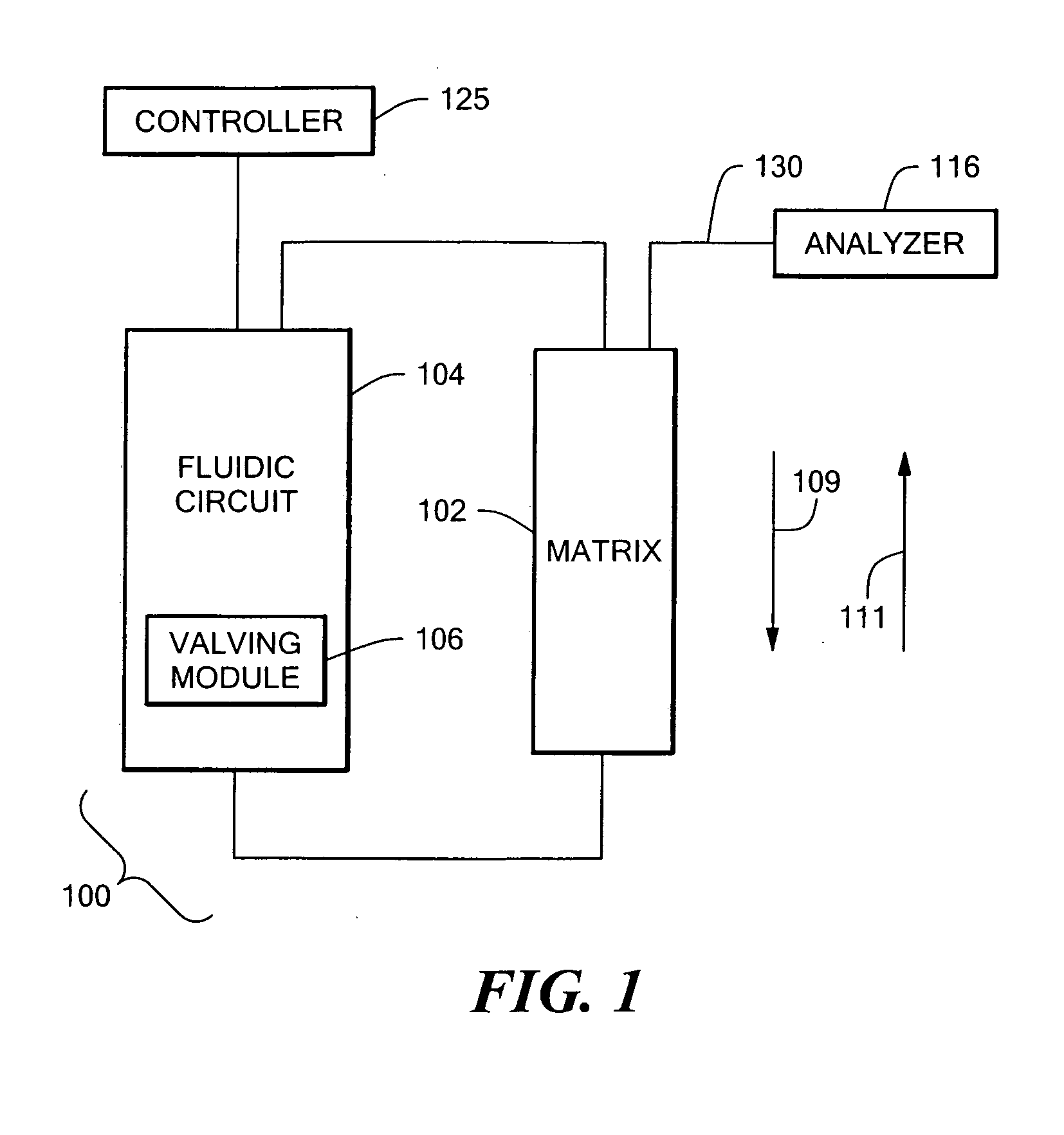
[0014] The current invention describes a system and method for increasing the throughput of analysis of selected components in complex biological, chemical, or environmental matrices with the use of, for example, chromatography and / or mass spectrometry. In various embodiments, throughput rates ranging from 30 seconds per sample to 1 second per sample or faster are achievable, depending on the specific application. Further embodiments of the invention include an auto-injection system that increases throughput and minimizes sample carryover.
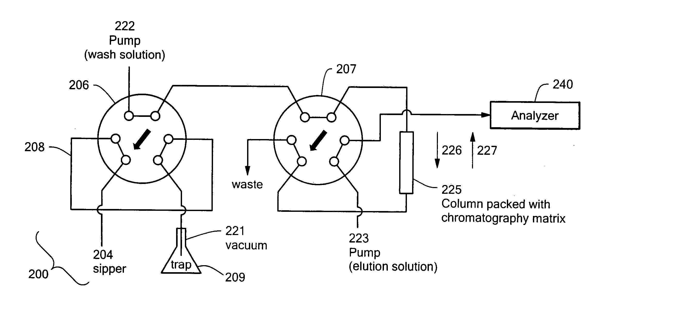
[0037] In a further such embodiment, the first position of the sample injection valve may further deliver wash buffer solution from the wash control valve to the sample chromatography column. The second position of the sample injection valve may further deliver elution solvent from the wash control valve to the sample supply loop. The first position of the column control valve may further supply elution solvent to flush the sample analyzer. The second position of the column control valve may further allow elution solvent to exit from the sample supply loop. The second position of the wash control valve may further deliver wash buffer solution to flush the sample supply loop.

Problems solved by technology

Auto-injectors commonly mimic cumbersome manual injection methods in which a metered aliquot of a sample is aspirated from a desired sample reservoir into a transfer syringe.
Contamination of the fluidic system with a sample can cause a significant barrier to the successful operation of a serial analysis system resulting in carryover and compromised data.
Throughput is thus increased through the parallelism of the process, however at increased cost and complexity.
Sequential analysis can be impractical and in many cases economically unviable if very large numbers of samples are to be analyzed.
Interference from high concentrations of non-volatile components are particularly troublesome because in addition to causing signal suppression non-volatile compounds tend to build up in the source region of the MS and gradually result in a decline in instrument performance.
For example, changes in pH, ionic strength, solvent composition, temperature, and / or other physicochemical parameters may weaken the affinity of the analyte(s) for the matrix.
However, the traditional use of liquid chromatography in high-throughput mass spectrometry has limitations.
Very often, the throughput of a serial analysis is limited by the time it takes to collect the signal from an individual sample.
If the throughput begins to approach the peak width, the sequential samples begin to overlap, baseline resolution between samples in the MS is lost, and accurate quantification for each sample is no longer possible.

Method used


Image

  • High throughput autosampler
  • High throughput autosampler
  • High throughput autosampler

Examples


example 1

Drug-Drug Interaction (DDI) Assay

[0096] Many xenobiotic compounds are metabolized in vivo by a family of enzymes known as cytochrome P-450s, primarily in the liver. The metabolic activity by P-450 enzyme also includes a vast majority of small molecule pharmaceuticals. Since the therapeutic activity of many pharmaceutically active compounds is highly dose-dependent it is advantageous to understand the metabolic fate of these chemicals. In many cases, high doses of certain chemicals can be toxic or have long-term deleterious effects.

[0097] Many compounds are known to affect the metabolism of certain P-450 enzymes, either acting as inhibitors or activators. This is true for a range of chemicals that are currently used as therapeutics. It is critical to know from a drug-safety standpoint whether or not the metabolic profile of a pharmaceutical compound taken by an individual may be affected by other chemicals that individual may be taking. If an individual is currently taking a certai...

example 2

Metabolic Stability Assay

[0107] In accordance with various embodiments of the invention, certain attributes of the system may be advantageously enhanced at the expense of throughput. An example of such an application is the metabolic stability assay. The metabolic stability assay assesses the activity of liver enzymes on a test molecule. It is typically an in vitro assay performed by incubating a sub-cellular liver preparation (e.g.: liver microsomes or S9 fraction) with a source of energy (e.g.: NADPH) and the test compound in an appropriate buffer system. The liver enzymes may metabolize the test compound, the rate of which can be determined by quantifying the amount of the test compound at controlled times using mass spectrometry.

[0108] This assay is different from the DDI assay in that each and every test compound must be monitored in the mass spectrometer. In the DDI assay, only a specific set of probes needed to be monitored allowing for a full optimization of the system. Gi...

example 3

Compound Purity Testing

[0115] In some applications the samples to be analyzed are already in a buffer that is compatible with mass spectrometry. Such an application may be the quality control analysis of test compounds in an aqueous or organic buffer that can directly be sprayed in to an API source without the need for any purification. Various aspects of the above-described embodiments can be used to increase the sample throughput for such an application.

[0116] In this application only a single injection valve is used. An aliquot of sample is aspirated into the injection loop and upon actuation of that valve the sample is sprayed directly in to the mass spectrometer. The flow from a single fluidic pump is used to push the sample through the injection loop and into the inlet of the mass spectrometer. In preferred embodiments of the invention, the fluid used to push the sample on to the mass spectrometer is one that the analytes are highly soluble in and provides good ionization in...


PUM

PropertyMeasurementUnit
actuation timeaaaaaaaaaa
diameteraaaaaaaaaa
flow ratesaaaaaaaaaa

Abstract

An auto-injection system provides high throughput screening of fluidic samples. A sample injection valve has a first position which applies a reduced pressure to a sample sipper tube for aspirating a fluidic sample into the sample sipper tube, and a second position which delivers the fluidic sample to a sample supply loop. A column control valve has a first position which delivers the fluidic sample from the sample supply loop to a sample chromatography column, and a second position which reverses direction of fluid flow through the sample chromatography column to deliver the fluidic sample to a sample analyzer. A wash control valve has a first position which supplies a wash buffer solution to the sample chromatography column in a forward fluid flow direction, and a second position which supplies elution solvent to flush the sample supply loop.

Description

CROSS REFERENCE TO RELATED APPLICATIONS [0001] This application claims priority from and is a continuation-in-part of U.S. patent application Ser. No. 10 / 984,027, filed Nov. 8, 2004, which in turn claimed priority from U.S. provisional patent application Ser. No. 60 / 518,240, entitled “High Throughput Sample Preparation and Analysis Using Chromatography,” filed Nov. 7, 2003, and which was also a continuation in part of U.S. patent application Ser. No. 10 / 267,912, entitled “System and Method for High Throughput Screening of Droplets,” filed Oct. 8, 2002, which is a continuation-in-part of U.S. patent application Ser. No. 09 / 842,361, filed Apr. 25, 2001, entitled “System and Method for High Throughput Processing of Droplets,” from which the present application additionally claims priority. Each of these patent applications described in this paragraph is hereby incorporated by reference, in its entirety.TECHNICAL FIELD [0002] The present invention relates generally to high throughput sc...

Claims


Application Information

Patent Timeline
Patent Type & Authority Applications(United States)
IPC IPC(8): B01J19/00C40B60/14G01N1/00G01N30/24G01N30/32G01N30/40G01N30/46G01N30/62G01N30/72G01N30/84G01N35/00G01N35/08G01N35/10
CPCB01F5/0085Y10T436/115831B01J19/0046B01J2219/0036B01J2219/00387B01J2219/00414B01J2219/00418B01J2219/00479B01J2219/00495B01J2219/00515B01J2219/00518B01J2219/00585B01J2219/0059B01J2219/00596B01J2219/00605B01J2219/00657B01J2219/00659B01J2219/00689B01J2219/00702B01J2219/0072B01L3/0262B01L3/0268B01L3/505B01L3/5085B01L2300/0812B01L2300/0845C40B60/14G01N30/24G01N30/40G01N30/466G01N30/7233G01N30/7266G01N30/84G01N35/00009G01N35/00584G01N35/08G01N35/1097G01N2030/324G01N2030/405G01N2030/626G01N2030/628G01N2030/8417G01N2035/1037G01N2035/1046H01J49/04B01F13/0059Y10T436/2575G01N30/18B01F25/14B01F33/30
Inventor OZBAL, CANGREEN, DONALD
Owner AGILENT TECH INC
Learn More