
Applicator head for applying fluid material to substrate

Inactive Publication Date: 2005-09-01
EFTEC NORTH AMERICA
View PDF41 Cites 35 Cited by
  • Summary
  • Abstract
  • Description
  • Claims
  • Application Information

AI Technical Summary

Benefits of technology

[0011] The invention also relates to a composition that has increased sound-damping efficacy after being baked for at least 10 minutes at a temperature of at least about 107° C. versus a pre-baked composition, said composition comprising a polymeric system, at least one low-density glass bead filler, at least one additional filler, and at least one rheological modifier, and wherein said composition has a density of from about 1 to about 2 g / cc.

Problems solved by technology

The construction of new die-cut pads, which correspond to various part layouts, can be expensive due to the complexity of the parts.
Also, the installation and replacement of these deadening pads can be labor intensive since the pads are manually applied.
However, these coatings often are expensive because of high material costs.
Furthermore, such coatings have low sound-damping characteristics and do not fully exceed the benefits of die-cut sound pads for the temperature range between −20° C. and 60° C. The use of these coatings has also raised environmental concerns.
Unused or scrap materials from an epoxy-based, liquid-applied sound-damping treatment are considered hazardous waste that requires special disposal methods.
However, such devices cannot apply high surface weight, waterborne compositions in a manner that provides controlled drying.
Moreover, when such devices are used to apply a bakeable, waterborne, liquid-applied sound-damping composition to the surface of an object, the sound transmission loss and damping properties of the composition are often compromised.

Method used


Image

  • Applicator head for applying fluid material to substrate
  • Applicator head for applying fluid material to substrate
  • Applicator head for applying fluid material to substrate

Examples


examples

[0057] Compositions A, B, and C of the invention comprise the following raw materials at the indicated levels. The compositions are obtained by first adding the liquid materials to a vessel, and mixing at room temperature. The powder filler materials are then added and mixed at room temperature until a smooth homogeneous paste is obtained. The Theological additives and water are then added with mixing to adjust the viscosity to about 60,000 centipoise and the density to about 1.3 g / cc.

Weight %Raw MaterialABCWater3.053.053.05Propylene glycol4.004.004.00Dispersant0.900.900.90Nonionic surfactant (30% sol. in water)0.900.900.90Attagel 30 rheology modifier2.502.502.50Acronal S504 binder (55% sol. in water)40.0035.0035.00Acronal A 378 binder (55% sol. in water)0.005.000.00GMA (55% sol. in water)0.000.005.00Biocide0.020.020.02Pigment0.200.200.20GPR 200 limestone filler31.8331.8331.83Water0.240.240.24Acrysol RM-8W rheology thickener0.080.080.08Dry ground mica 4K filler12.3112.3112.31Expan...


PUM

PropertyMeasurementUnit
Temperatureaaaaaaaaaa

Abstract

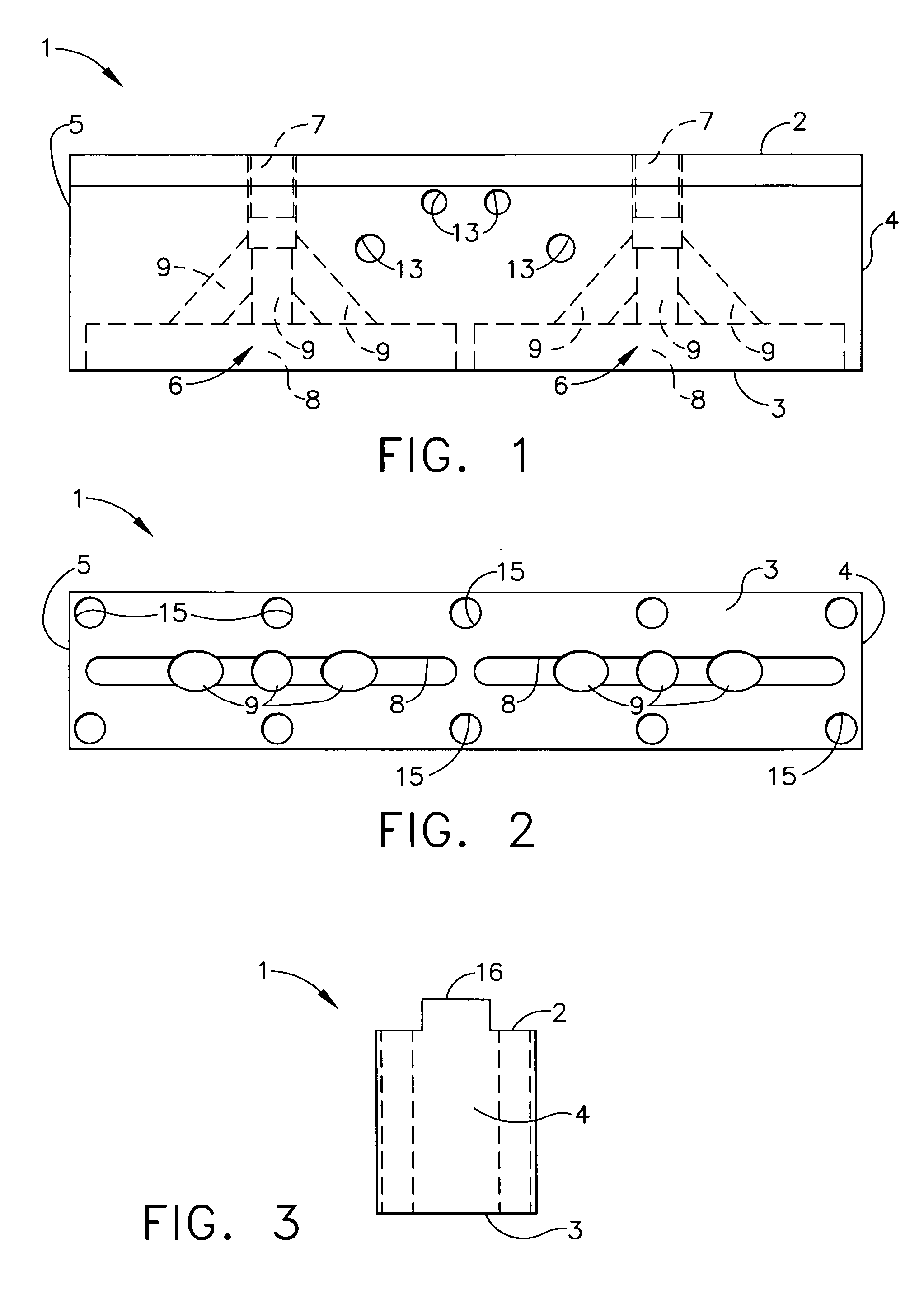
An applicator head for connection to a robotic device, and useful for applying a fluid material to a substrate. The applicator head comprises: (a) a body portion; (b) at least one material delivery system comprising an inlet, a fluid delivery cavity, and two or more passageways connecting the inlet to the fluid delivery cavity; and (c) a nozzle plate attached to the bottom surface of the body portion, and having a plurality of openings communicating with the fluid delivery cavity. In one embodiment, the applicator head comprises a nozzle inserted in each of the plurality of openings in the nozzle plate, with each nozzle adapted to apply a bead of a fluid material to a substrate, with the beads spaced less than about 2 mm apart. Also disclosed is a sound-damping composition comprising: (a) n-butyl acrylate-acrylonitrile-styrene copolymer; (b) at least about 0.5% by weight of a low-density glass bead filler; (c) at least one additional filler; and (d) at least one rheological modifier; and having a density of from about 1 to about 2 g / cc. Methods for applying the sound-damping composition by extruding it onto a substrate and baking it to exhaust water in a controlled manner, and methods for increasing the sound-damping efficacy of an aqueous polymeric composition, are also disclosed.

Description

FIELD OF THE INVENTION [0001] The invention relates to an applicator head for connection to a robotic device. The applicator head is useful for applying a fluid material, such as a bakeable, waterborne, liquid-applied sound-damping composition, to a substrate. The invention also relates to such a sound-damping composition, a method for applying it to a substrate, and a method for increasing sound-damping efficacy. BACKGROUND OF THE INVENTION In order to decrease the noise associated with vibration in various industrial machines, vehicles, and appliances, manually applied die-cut mastic or asphaltic sound deadening pads have been employed. The construction of new die-cut pads, which correspond to various part layouts, can be expensive due to the complexity of the parts. Also, the installation and replacement of these deadening pads can be labor intensive since the pads are manually applied. [0002] To decrease vibration noise, vibration damping coatings, including low-frequency, vibra...

Claims


Application Information

Patent Timeline
IPC IPC(8): B05B1/20B05B3/00B05B13/04B05B15/06B05B15/68C09D5/00C09D7/43C09D7/61
CPCB05B1/202B05B13/0431B05B15/065C09D7/1291C08K3/14C09D5/00C08K3/0033C09D7/70C08K3/013B05B15/65C09D7/43C09D7/61
Inventor HUSSAINI, AKBAR SYEDRODRIGUES, SILVEIROANTOINIE, MICHAEL JESS
Owner EFTEC NORTH AMERICA
Learn More