
Custom in-ear headset

Active Publication Date: 2011-06-09
INVISIO COMM
View PDF10 Cites 43 Cited by
  • Summary
  • Abstract
  • Description
  • Claims
  • Application Information

AI Technical Summary

Benefits of technology

[0022]The at least one ridge is preferably unbroken to provide effective acoustical sealing around the entire circumference of the distant housing portion but may alternatively include one or more minor gaps and still provide a certain degree of improvement of the acoustical sealing properties of the housing of the present custom in-ear headset.
[0023]As mentioned above, the at least one ridge provides a surprising improvement of the acoustical sealing of the user's ear canal when pressed against a cartilaginous portion of the user's ear canal. This effect is accordingly obtained by shaping and sizing the housing so as to fit the ridge(s) in a cartilaginous portion of the ear canal of the user. Given the anatomy of the human ear, the cartilaginous portion of a human ear canal is situated outwardly relative to a second bend of the ear canal toward an ear canal entrance. According to this definition, the second bend is the bend closest to the ear drum. An appropriate way of shaping and sizing the housing may comprise making an ear canal impression and building a corresponding mould with at least one ridge formed therein. An appropriate position of the ridge(s) may be determined by a skilled ear plug / shell technician from inspection of features and dimensions of the ear impression or in other suitable ways.
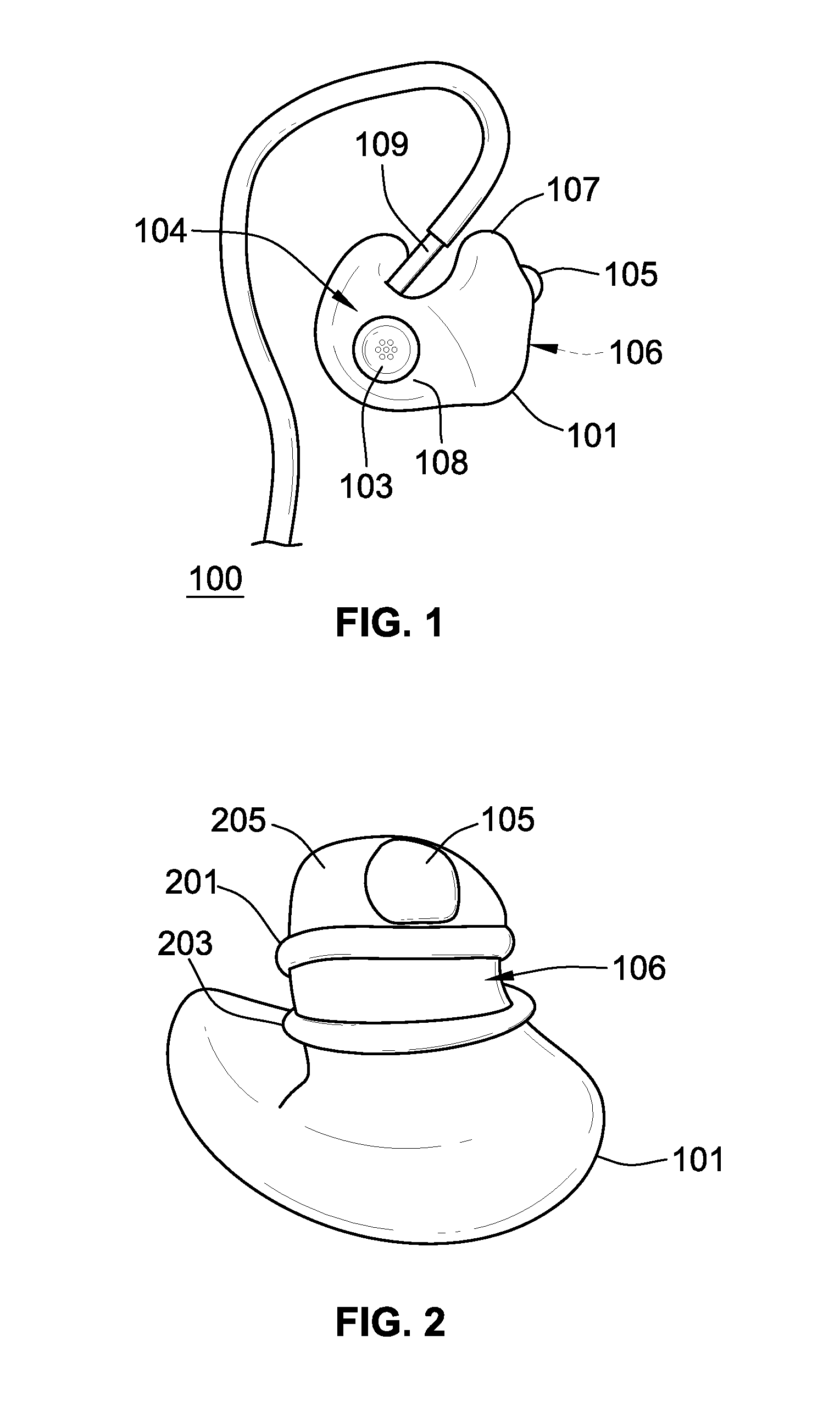
[0026]According to a preferred embodiment of the invention, the distant housing portion comprises a first and a second ridge (or even further ridges) projecting from and circumscribing the distant housing portion to further improve the acoustical sealing or sound attenuation of the housing during normal operation in the user's ear. The second ridge may have approximately identical dimensions to the first ridge in terms of width and height or the second ridge may have different dimensions. Due to an often highly irregular shape of the distant housing portion (conforming to the irregular shape of the user's ear canal) and the distance between the first and second ridges their circumference may be quite different. The first and second ridges may be oriented essentially equidistant from each other, i.e. parallelly oriented, or the distance may vary even widely around the distal housing circumference. In both cases, the smallest distance between the first and second ridges, measured in tangential direction to the first ridge, is preferably larger than 1.0 mm and less than 5.0 mm.
[0027]Several variations or embodiments for picking up the user's voice in the present custom in-ear head set are possible. In one embodiment, the microphone with a sound inlet located in the proximate housing portion (“proximate microphone”) is adapted to pick-up and transmit the user's voice, and other environmental sounds, to a distant listener. This microphone placement generally allows receipt and transmission of the user's voice in full bandwidth and therefore good fidelity. However, environmental sound such as competing noise sources are picked-up equally well and may lead to lower fidelity and intelligibility if the user is located in a noisy environment like a train station, bar, etc.
[0033]A further improvement in suppression of environmental sound is obtained in an embodiment wherein the bone conduction microphone comprises a vibration pickup member located distantly relative to a first ridge in a direction toward the tip of the housing or the distal microphone has the sound inlet located distantly relative to the first ridge in a direction toward the tip of the housing. The location of the vibration pickup member or the sound inlet behind the first ridge, or behind both of the first and second ridge in embodiments comprising two ridges, provides additional attenuation of environmental sound and noise, including the user's airborne voice, at the sound inlet of the distal microphone or at the vibration pick-up member. Since any practical bone conduction microphone has a certain (undesired) sensitivity to airborne sound, the additional sound attenuation provided by the first ridge is very advantageous. As previously mentioned, good suppression of environmental noise leads to superior noise suppression in the microphone signal to be transmitted to the distant listener so as to allow speech of high fidelity and intelligibility from the bone conduction microphone to be transmitted to the distant listener even when the user is located in a very noisy acoustical environment.

Problems solved by technology

However, creating effective sound sealing around the housing of prior art in-ear headset devices to block or suppress leakage of environmental noise to the user's essentially occluded ear canal remains a significant challenge.
Since an airborne sound microphone inside the user's ear canal is inherently sensitive to airborne sound and any practical bone conduction microphone also has a certain (undesired) sensitivity to airborne sound, acoustical leakage of environmental sound around the housing will decrease the fidelity and intelligibly of the sound picked up.
One obstacle to reach effective sound sealing or sound attenuation is the varying or dynamic geometry or shape of the user's ear canal caused by user activity such as chewing, eating, yawning etc which leads to the formation of a time-varying acoustic leakage path around the housing.
Another obstacle to effective sound sealing is user comfort.
Even though a very tightly fitted housing geometry, for example a deliberately oversized housing geometry, could provide good sound sealing it has proven to lead to unacceptable wearing comfort by exerting painful pressure on a large portion of the user's ear canal.

Method used


Image

  • Custom in-ear headset
  • Custom in-ear headset

Examples


Embodiment Construction

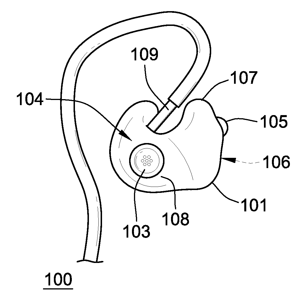
[0052]FIG. 1 shows a custom in-ear headset 100 comprising a headset housing 101 having a proximate housing portion 104 and a distant housing portion 106. The distant housing portion, as indicated by arrow 106, is generally the part being closest to the user when the in-ear headset 100 is worn by the user while the proximate housing portion, as indicated by hashed arrow 104, is generally the part being furthest away from the user when the in-ear headset is worn by the user. The proximate housing portion 104 is terminated by a closed shell face 108 that point outwardly of the user's ear when the custom in-ear headset 100 is mounted therein. The distant housing portion 106 has a tapering outer contour terminating in a tip 205 (refer to FIG. 2) also comprising a sound outlet (not shown) of a miniature speaker (not shown) for conveying sound pressure to the user's substantially occluded ear canal. The tip 205 is accordingly the most distant portion of the headset housing 101 and generall...


PUM


Abstract

A custom in-ear headset. The headset includes a housing having a proximate housing portion and a distant housing portion. The distant housing portion is shaped and sized to fit inside an ear canal of a user. The headset includes a miniature speaker that is acoustically coupled to a sound outlet in the distant portion of the housing for conveying sound pressure to an ear canal of the user. The headset further includes any one or more of: (a) a microphone with a sound inlet in the proximate housing portion, (b) a bone conduction microphone arranged in the distant housing portion, or (c) a microphone with a sound inlet in the distant housing portion. The headset further includes at least one ridge projecting from and circumscribing the distant housing portion.

Description

CROSS-REFERENCE TO RELATED APPLICATION[0001]This application claims the benefit of U.S. Provisional Application Ser. No. 61 / 267,976, filed Dec. 9, 2009, entitled “A Custom In-Ear Headset.”COPYRIGHT[0002]A portion of the disclosure of this patent document contains material which is subject to copyright protection. The copyright owner has no objection to the facsimile reproduction by anyone of the patent disclosure, as it appears in the Patent and Trademark Office patent files or records, but otherwise reserves all copyright rights whatsoever.FIELD OF THE INVENTION[0003]The present invention relates to a custom in-ear headset which comprises a distant housing portion with a ridge projecting from and circumscribing the distant housing portion. The distant housing portion is shaped and sized to fit inside an ear canal of a user so as to acoustically seal the user's ear canal against environmental sound.BACKGROUND OF THE INVENTION[0004]Custom in-ear headsets are well-known in the art and...

Claims


Application Information

Patent Timeline
IPC IPC(8): H04R1/10G10K11/162
CPCH04R1/1016H04R2460/13H04R1/1058B33Y80/00
Inventor LARSENSPARRE, JON HJERSINGIVERSEN, STEEN
Owner INVISIO COMM
Learn More