
Transition metal-containing catalysts and processes for their preparation and use as oxidation and dehydrogenation catalysts

a technology of transition metal and catalyst, which is applied in the field of heterogeneous catalysis, can solve the problems of high loss of costly noble metal into the reaction solution, undesirable formaldehyde by-product, and undesirable formaldehyde by-produ

Active Publication Date: 2005-08-11
MONSANTO TECH LLC
View PDF38 Cites 62 Cited by
  • Summary
  • Abstract
  • Description
  • Claims
  • Application Information

AI Technical Summary

Benefits of technology

[0033] This invention provides catalysts and methods for preparing catalysts that are useful in various heterogeneous oxidation and dehydrogenation reactions, including the preparation of secondary amines by the catalytic oxidation of tertiary amines and the preparation of carboxylic acids by the catalytic dehydrogenation of primary alcohols. The catalysts include supports, particularly carbon supports, having formed thereon compositions which comprise a transition metal in combination with nitrogen and/or carbon and optionally a further metal deposited on the mo

Problems solved by technology

Even though the Franz method produces an acceptable yield and purity of N-(phosphonomethyl)glycine, high losses of the costly noble metal into the reaction solution (i.e., “leaching”) result because under the oxidation conditions of the reaction, some of the noble metal is oxidized into a more soluble form and both PMIDA and N-(phosphonomethyl)glycine act as ligands which solubilize the noble metal.
This formaldehyde by-product is undesirable because it reacts with N-(phosphonomethyl)glycine to produce unwanted by-products (mainly N-methyl-N-(phosphonomethyl)glycine, sometimes referred to as “NMG”) which reduce the N-(phosphonomethyl)glycine yield.
In addition, the formaldehyde by-product itself is undesirable because of its potential toxicity.
Previous attempts to develop a stable catalyst for such an oxidation process, however, have not been entirely satisfactory.
Still, the amount of noble metal loss incurred with this method is unacceptable.
In addition, re-depositing the noble metal can lead to loss of noble metal surface area which, in turn, decreases the activity of the catalyst.
This approach, however, suffers from several disadvantages: (1) it is difficult to recover the costly noble metal from the aluminosilicate support for re-use; (2) it is difficult to design the two catalysts so that the rates between them are matched; and (3) the carbon support, which has no noble metal deposited on its surface, tends to deactivate at a rate which can exceed 10% per cycle.
Chitwood, however, reported that copper-containing compounds are disadvantageous for this reaction because the copper coagulates over time, thereby causing the copper-containing compounds to have a short duration of maximum catalytic activity.
Raney copper, however, is disadvantageous because (like Chitwood's copper-containing compounds) Raney copper deactivates over time.
Although these developments have made the use of copper catalysts more commercially viable, their results are still not entirely satisfactory.
Although the Ebner catalysts afford shorter reaction times relative to previously disclosed copper-containing catalysts, their catalyst may be relatively expensive due to the need for the noble metal to anchor the copper to the support.
As with the Franczyk catalysts, this problem tends to arise particularly where the primary alcohol or the dehydrogenation salt product is a chelating agent.
However, it has been discovered that the catalyst described by Morgenstern et al. may lead to the production of unwanted byproducts (e.g., sarcosine) which may have an adverse impact on processes incorporating a carboxylic acid salt produced using this catalyst.
These supports, however, tend to be vulnerable to attrition under the reaction conditions normally present when dehydrogenating a primary alcohol, and are therefore usually less suitable than Ebner et al.
Vulnerability to attrition tends to also cause these supports to exhibit poor filtration characteristics.

Method used


Image

  • Transition metal-containing catalysts and processes for their preparation and use as oxidation and dehydrogenation catalysts
  • Transition metal-containing catalysts and processes for their preparation and use as oxidation and dehydrogenation catalysts
  • Transition metal-containing catalysts and processes for their preparation and use as oxidation and dehydrogenation catalysts

Examples


example 1

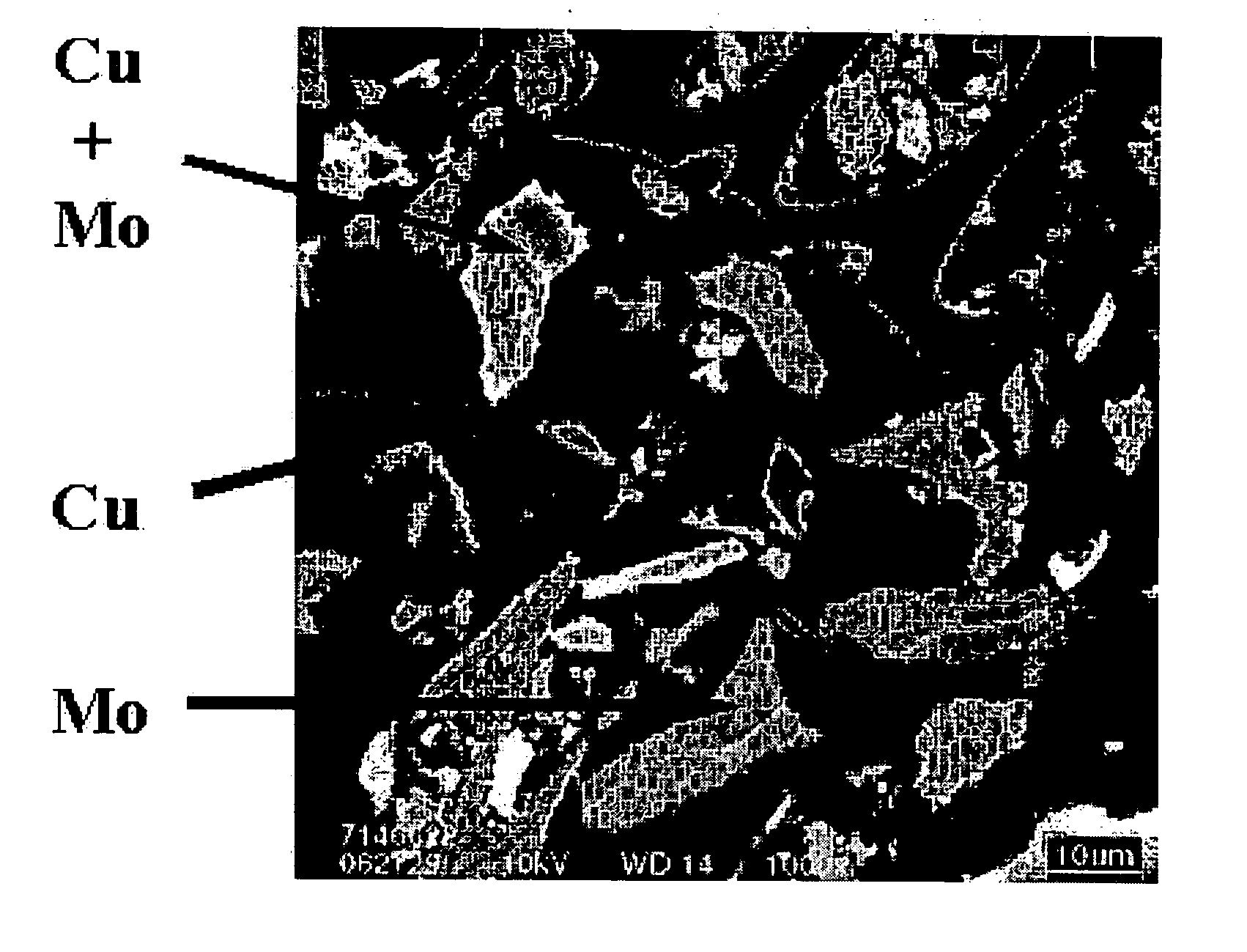
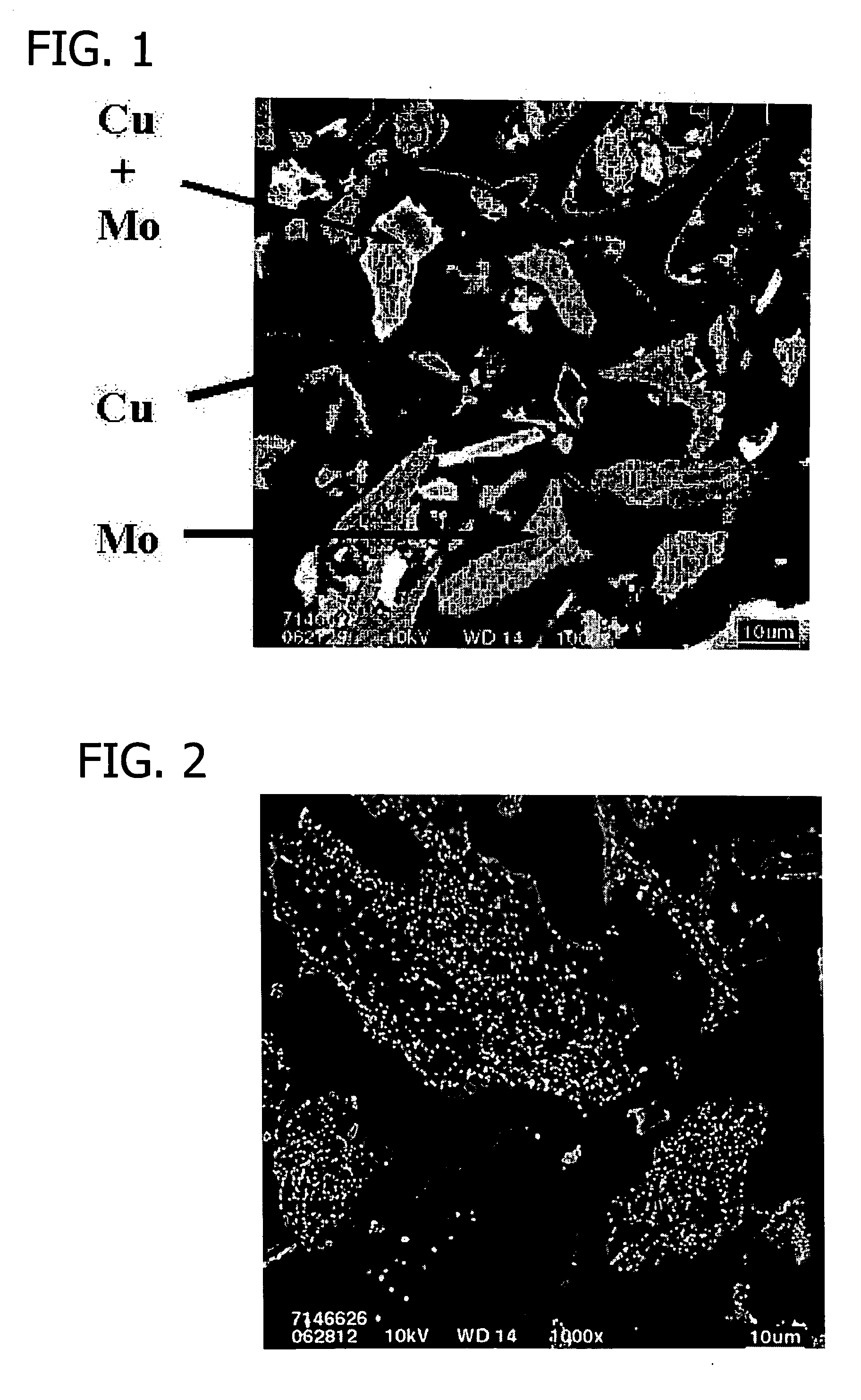
Electroless Copper Plating on Bulk Metal Carbides and Nitrides

[0354] This example details electroless copper plating on bulk metal carbides and nitrides.

[0355] Bulk molybdenum carbide (20.0 g) (Aldrich Chemical Co., Milwaukee, Wis.) was added to a 2 l flask containing deionized water (200 ml) and a magnetic stirring bar to form a slurry.

[0356] A copper plating solution was prepared by adding reagent grade sodium potassium tartrate (NaKC4H4O6.4H2O) (29.99 g) (Aldrich Chemical Co., Milwaukee, Wis.), copper sulfate (CuSO4.5H2O) (11.79 g) (Aldrich Chemical Co., Milwaukee, Wis.), a 50 wt. % solution of sodium hydroxide (NaOH) (13.60 g) (Aldrich Chemical Co., Milwaukee, Wis.) and 37 wt. % formaldehyde (CH2O) (11.35 ml) (Aldrich Chemical Co., Milwaukee, Wis.) to deionized water (950 ml) to form approximately 1 liter of plating solution in a 2 liter flask.

[0357] Plating solution was added to the carbide slurry incrementally over the course of about 40 minutes with approximately 60 ml of...

example 2

Synthesis of a Precursor for Use in Preparing Carbon-Supported Molybdenum Carbides (Mo2C / C) and Carbon-Supported Molybdenum Nitrides (Mo2N / C)

[0360] This example details the preparation of a precursor for use in preparing carbon-supported molybdenum carbides and nitrides.

[0361] A carbon support (20.0 g) having a B.E.T. surface area of 1067 m2 / g (Degussa Corporation) was added to a 1 l beaker containing deionized water (300 ml) and a magnetic stirring bar to form a slurry.

[0362] A solution (60 ml) containing ammonium molybdate ((NH4)2MoO4) (4.236 g) (Aldrich Chemical Co., Milwaukee, Wis.) in deionized water was added to the carbon slurry using a MasterFlex® meter pump (MasterFlex® L / S®) manufactured by Cole-Parmer Instrument Company (Vernon Hills, Ill.). The slurry was agitated by a mechanical stirrer while the molybdenum solution was added to the carbon slurry at a rate of 2.0 ml / min over the course of about 30-40 minutes. During addition of the molybdenum solution to the carbon s...

example 3

Synthesis of Carbon-Supported Molybdenum Carbide Containing 15% by Weight Molybdenum Carbide (15% Mo2C / C)

[0365] This example details preparation of a carbon-supported molybdenum carbide using a carbon-supported molybdenum carbide precursor prepared in accordance with the procedure set forth above in Example 2.

[0366] The carbide precursor (8.0 g) was charged into a Hastelloy C tube reactor packed with high temperature insulation material which was purged with argon introduced to the reactor at 100 cm3 / min at about 20° C. for approximately 15 minutes. A thermocouple was inserted into the center of the reactor for charging of the precursor material.

[0367] The temperature of the reactor was then raised to about 300° C. over the course of 30 minutes during which time a 50% / 50% (v / v) mixture of methane and hydrogen (Airgas Co., St. Louis, Mo.) was introduced to the reactor at a rate of about 100 cm3 / min.

[0368] The temperature of the reactor was then increased to approximately 650° C. ...


PUM

PropertyMeasurementUnit
Temperatureaaaaaaaaaa
Fractionaaaaaaaaaa
Fractionaaaaaaaaaa

Abstract

This invention relates to the field of heterogeneous catalysis, and more particularly to catalysts including carbon supports having formed thereon compositions which comprise a transition metal in combination with nitrogen and / or carbon. The invention further relates to the fields of catalytic oxidation and dehydrogenation reactions, including the preparation of secondary amines by the catalytic oxidation of tertiary amines and the preparation of carboxylic acids by the catalytic dehydrogenation of alcohols.

Description

REFERENCE TO RELATED APPLICATION [0001] This application claims the benefit of U.S. Provisional Application Ser. No. 60 / 495,481, filed Aug. 14, 2003, the entire contents of which are incorporated herein by reference.FIELD OF INVENTION [0002] This invention relates to the field of heterogeneous catalysis, and more particularly to catalysts including carbon supports having formed thereon compositions which comprise a transition metal in combination with nitrogen and / or carbon. The invention further relates to the fields of catalytic oxidation and dehydrogenation reactions, including the preparation of secondary amines by the catalytic oxidation of tertiary amines and the preparation of carboxylic acids by the catalytic dehydrogenation of alcohols. BACKGROUND OF INVENTION [0003] Investigations to discover alternative materials for use in catalysis concerning various types of reactions have included evaluation of the suitability of carbide and nitride materials. Generally, carbide and n...

Claims


Application Information

Patent Timeline
IPC IPC(8): B01J21/18B01J23/40B01J23/72B01J27/22B01J27/24B01J35/02B01J35/10B01J37/08C07C209/68C07C249/02C07C251/06C07F9/38
CPCB01J21/18B01J23/40C07F9/3813B01J23/72B01J27/22B01J27/24B01J35/023B01J35/1023B01J35/1028B01J37/084B82Y30/00C07C209/68C07C249/02C07C251/06Y02P20/582Y02E60/50B01J35/40B01J35/617B01J35/618
Inventor COLEMAN, JAMES P.MCGRATH, MARTIN P.LIU, FUCHENARHANCET, JUAN
Owner MONSANTO TECH LLC
Learn More