
Material for organic electroluminescent element and organic electroluminescent element employing the same

Inactive Publication Date: 2005-07-21
IDEMITSU KOSAN CO LTD
View PDF11 Cites 48 Cited by
  • Summary
  • Abstract
  • Description
  • Claims
  • Application Information

AI Technical Summary

Benefits of technology

[0034] In contrast, it is considered that, by using the material of the present invention for the phosphorescence device, the efficiency of light emission three times as great as that of a device using fluorescence can be obtained since the triplet exciton can be used for the emission of light. It is also considered that, when the compound of the present invention is used for the light emitting layer of the phosphorescence device, an excited triplet level in an energy state higher than the excited triplet level of a phosphorescent organometallic complex comprising a metal selected from the Group 7 to 11 of the Periodic Table contained in the layer, is achieved; the film having a more stable form is provided; the glass transition temperature is higher (Tg: 80 to 160° C.); holes and / or electrons are efficiently transported; the compound is electrochemically and chemically stable; and the formation of impurities which may work as a trap or cause loss in the light emission is suppressed during the preparation and the use.
[0037] For the light emitting layer, in addition to the material of the present invention comprising the compound represented by general formula (1) or (2), well known host materials, light emitting materials, doping materials, hole injecting materials and electron injecting materials and combinations of these materials may be used in combination, where necessary. By using a multi-layer structure for the organic EL device, decreases in the luminance and the life due to quenching can be prevented, and the luminance of emitted light and the efficiency of light emission can be improved with other doping materials. By using other doping materials contributing to the light emission of the phosphorescence in combination, the luminance of emitted light and the efficiency of light emission can be improved in comparison with those of conventional devices.
[0054] The property of charge injection can be improved by adding an electron-accepting compound to the hole injecting material and an electron-donating compound to the electron injecting material.
[0059] In the organic EL device of the present invention, it is possible that a protective layer is formed on the surface of the device or the entire device is covered with a silicone oil or a resin so that stability to the temperature, the humidity and the atmosphere is improved.
[0061] When the wet process of film formation is used, the material forming each layer is dissolved or suspended in a suitable solvent such as ethanol, chloroform, tetrahydrofuran and dioxane, and a thin film is formed from the obtained solution or suspension. Any of the above solvents can be used. For any of the layers, suitable resins and additives may be used to improve the property for film formation and to prevent formation of pin holes in the film. Examples of the resin which can be used include insulating resins such as polystyrene, polycarbonates, polyarylates, polyesters, polyamides, polyurethanes, polysulfones, polymethyl methacrylate, polymethyl acrylate, cellulose and copolymer resins derived from these resins; photoconductive resins such as poly-N-vinylcarbazole and polysilanes; and electrically conductive resins such as polythiophene and polypyrrol. Examples of the additive include antioxidants, ultraviolet light absorbents and plasticizers.

Problems solved by technology

However, the efficiency of light emission, the life and the purity of blue light are insufficient for the practical application.
However, the efficiency of light emission is as insufficient as 2 to 4 cd / A.
However, this device emits yellow to green light and cannot emit blue light having a sufficiently high purity of color.

Method used


Image

  • Material for organic electroluminescent element and organic electroluminescent element employing the same
  • Material for organic electroluminescent element and organic electroluminescent element employing the same
  • Material for organic electroluminescent element and organic electroluminescent element employing the same

Examples


synthesis example 1

Synthesis of Compound (A1)

[0067] The route of synthesis of Compound (A1) is shown in the following.

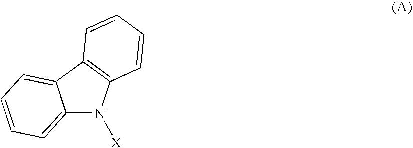
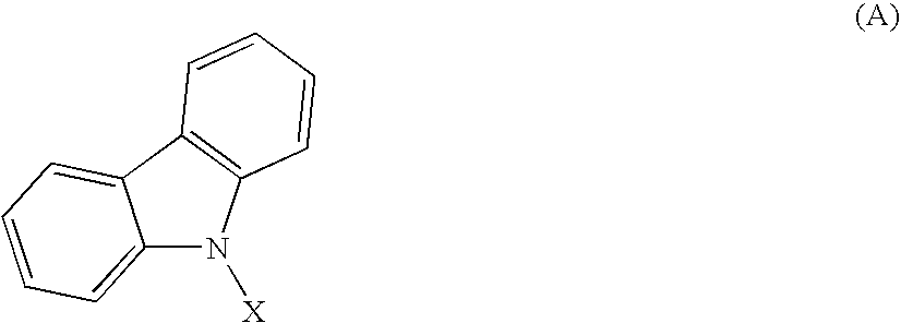
[0068] Into a reactor, 3.92 g (10 mmole) of 1,l-bis(p-bromophenyl)-cyclohexane, 4.0 g (24 mmole) of carbazole, 0.6 g of copper powder, 1.7 g of 18-crown-6 and 2.9 g (21 mmole) of potassium carbonate were placed. After 50 milliliter of o-dichlorobenzene as the solvent was added, the resultant mixture was heated at 200° C. in a silicone oil bath under a stream of nitrogen, and the reaction was allowed to proceed for 48 hours. After the reaction was completed, the reaction mixture was filtered before the mixture was cooled, and the obtained filtrate was concentrated using a rotary evaporator. To the obtained oily product, 30 milliliter of methanol was added. The formed solid substance was separated by filtration under a reduced pressure, and a gray solid substance was obtained. The obtained solid substance was recrystallized from benzene, and 2.6 g (4.6 mmole) (the yield: 46%) of white...

synthesis example 2

Synthesis of Compound (A4)

[0071] The route of synthesis of Compound (A4) is shown in the following.

[0072] The reaction was conducted under the same conditions as those in Synthesis Example 1 except that 1,3-dibromoadamantane was used in place of 1,1-bis(p-bromophenyl)cyclohexane and 3,6-diphenylcarbazole was used in place of carbazole. The obtained solid substance was recrystallized from toluene, and 1.9 g (the yield: 25%) of white crystals were obtained. It was confirmed in accordance with 90 MHz 1H-NMR and FD-MS that the obtained crystals were Compound (A4) of the object compound. The result of the measurement by FD-MS is shown in the following.

[0073] FD-MS calcd. for C58H48N2=770; found: m / z=770 (M+, 100)

[0074] The singlet energy gap and the triplet energy gap of the obtained compound are shown in Table 1.

synthesis example 3

Synthesis of Compound (B1)

[0075] The route of synthesis of Compound (B1) is shown in the following.

[0076] 3,6-Dibromo-N-phenylcarbazole in an amount of 4 g (10 mmole) was dissolved into 50 milliliter of dehydrated tetrahydrofuran (THF). To the resultant solution, a solution obtained by dissolving 5.8 g (24 mmole) of 1-adamantylmagnesium bromide into 20 milliliter of THF was added dropwise. The obtained mixture was stirred under the refluxing condition under a stream of nitrogen for 12 hours, and the reaction was allowed to proceed for 12 hours. After the reaction was completed, 6N hydrochloric acid was added to the reaction mixture, and the obtained mixture was stirred. The formed organic layer was separated, washed with water and dried with anhydrous magnesium chloride. The solvent was removed by distillation from the obtained extract using a rotary evaporator, and a brown solid substance was obtained. The obtained solid substance was recrystallized from benzene, and 1.1 g (the ...


PUM

PropertyMeasurementUnit
Energy gapaaaaaaaaaa
Areaaaaaaaaaaa

Abstract

A material for electroluminescent which comprises a compound in which a cycloalkyl group or a meta-phenylene group is bonded to a group having carbazole skeleton structure and an organic electroluminescent device having an organic thin film layer having at least one layer which is sandwiched between the cathode and the anode and contains the above material in at least one layer, are provided. The material can provide organic electroluminescent devices emitting bluish light with a high purity of color. The organic electroluminescence device uses the material.

Description

TECHNICAL FIELD [0001] The present invention relates to a material for organic electroluminescent elements (“electroluminescent” will be referred to as “EL”, and “element” will be referred to as “device”, hereinafter) and an organic EL device employing the material and, more particularly, to an organic EL device emitting bluish light with a high purity of color. BACKGROUND ART [0002] Organic EL devices which utilize organic substances are expected to be useful for application as an inexpensive full color display device of the solid light emission type having a great size, and various developments on the organic EL devices are being conducted. In general, an organic EL device has a construction comprising a pair of facing electrodes and a light emitting layer sandwiched between the electrodes. [0003] The light emission of the organic EL device is a phenomenon in which, when an electric field is applied across the two electrodes, electrons are injected from the cathode side and holes ...

Claims


Application Information

Patent Timeline
IPC IPC(8): C09K11/06H01L51/00H01L51/30H01L51/50H05B33/14
CPCC09K11/06C09K2211/1007C09K2211/1011C09K2211/1014C09K2211/1029H01L51/0059H05B33/14H01L51/0081H01L51/0084H01L51/0085H01L51/5012H01L51/5016H01L51/5048H01L51/0072H10K85/631H10K85/324H10K85/341H10K85/342H10K85/6572H10K50/14H10K50/11H10K2101/10
Inventor IWAKUMA, TOSHIHIROHIRONAKA, YOSHIOHOSOKAWA, CHISHIOTOMITA, SEIJIARAKANE, TAKASHI
Owner IDEMITSU KOSAN CO LTD
Learn More