Method and apparatus for recording/reproducing optical information

Inactive Publication Date: 2005-07-21
NEC CORP
View PDF5 Cites 1 Cited by
  • Summary
  • Abstract
  • Description
  • Claims
  • Application Information

AI Technical Summary

Benefits of technology

[0008] The present invention has been developed in consideration of the above-described problems, and an object thereof is to provide an optical information recording medium capable of setting recording and reproducing characteristics of a portion corresponding to a flat portion between guide grooves to be substantially equal to those of a portion corresponding to the inside of the guide groove, thereby raising a track density, and further enhancing a linear recording density to make it possible to perform recording with a high density in a case where the recording is performed into both a recording layer portion corresponding to the flat portion between the guide grooves and a recording layer portion corresponding to the inside of the guide groove at a high recording density.

Problems solved by technology

However, according to findings of the present inventors, in the case where the land / groove recording is performed using the high-NA optical head, there is a problem that an optical resolution differs with the recording in a recording layer portion corresponding to the flat portion between the guide grooves and the recording in a recording layer portion corresponding to the inside of the guide groove.
When the signal amplitude in a short mark remarkably drops in the recording into the portion corresponding to the flat portion between the guide grooves, a sufficient signal quality is not obtained, and therefore a problem has occurred that the high-density recording cannot be performed.
Even in a case where the laser light is applied to the substrate from its back surface in the same manner as in the conventional DVD, when the recording density is raised, that is, when a shortest mark length recorded into the disk shortens, the problem becomes remarkable.

Method used


Image

  • Method and apparatus for recording/reproducing optical information
  • Method and apparatus for recording/reproducing optical information
  • Method and apparatus for recording/reproducing optical information

Examples


example 1

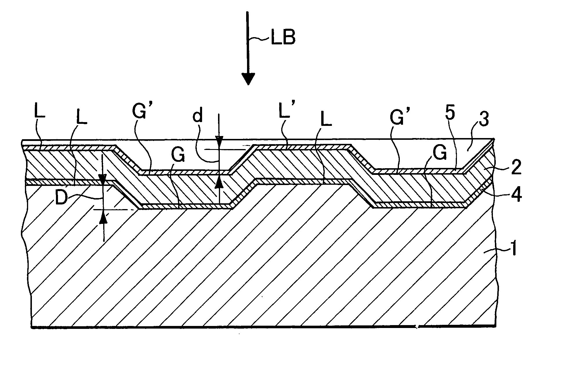
[0059] A disc-shaped PC substrate having a thickness of 1.1 mm was used as a substrate, and a 100 nm thick Al reflective film, a 15 nm thick ZnS—SiO2 dielectric layer, a 15 nm thick GeSbTe recording layer, and a 40 to 85 nm thick ZnS—SiO2 dielectric layer were stacked / formed on a land / groove formed surface of the substrate by sputtering. On the layers, a 0.1 mm thick PC film was bonded as a light-transmitting layer by an ultraviolet cured resin.

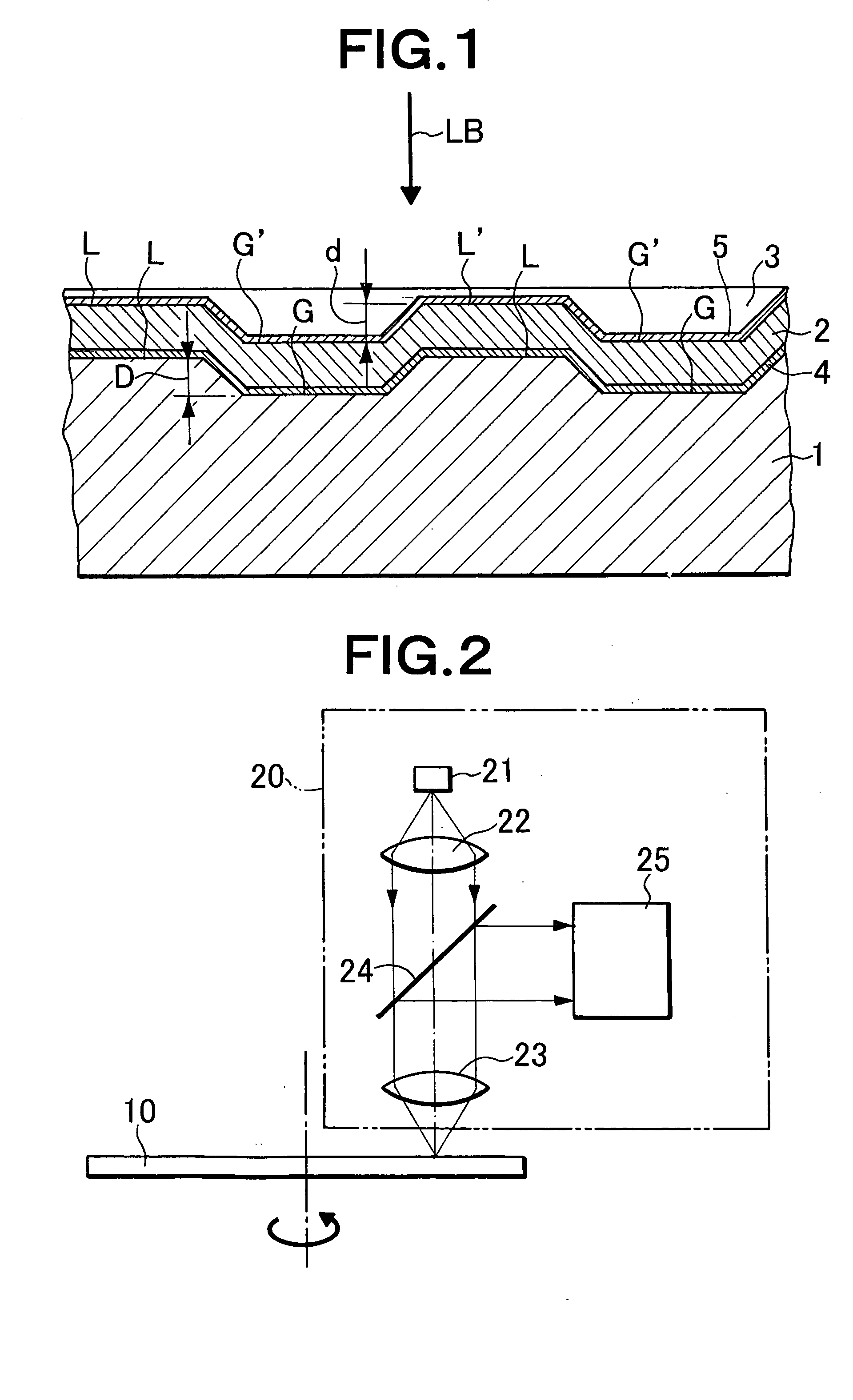
[0060] After initializing (crystallizing) the above-described disk (recording medium), the disk was rotated at a linear speed of 5.1 m / s, laser light was applied from a light-transmitting layer side using an optical head having a wavelength of 405 nm, NA=0.85, recording was performed into both a portion L′ corresponding to a land and a portion G′ corresponding to a groove on a linear density condition of 0.116 μm / bit, and reproduction characteristics were measured. Since (1-7) modulation was used as a modulation system, a mark length of a lo...

example 2

[0064] A disc-shaped PC substrate having a thickness of 1.1 mm was used as a substrate, and a 100 nm thick Al reflective film, a 25 nm thick ZnS—SiO2 dielectric layer, a 15 nm thick GeSbTe recording layer, a 25 nm thick ZnS—SiO2 dielectric layer, a 30 nm thick SiO2 dielectric layer, and a 50 to 75 nm thick ZnS—SiO2 dielectric layer were successively stacked / formed on a land / groove formed surface of the substrate by sputtering. On the layers, a 0.1 mm thick PC film was bonded as a light-transmitting layer by an ultraviolet cured resin.

[0065] After initializing (crystallizing) the above-described disk, the dark was rotated at a linear speed of 5.1 m / s, laser light was applied from a light-transmitting layer side using an optical head having a wavelength of 405 nm, NA=0.85, recording was performed into both a portion L′ corresponding to a land and a portion G′ corresponding to a groove on a linear density condition of 0.116 μm / bit, and reproduction characteristics were measured. Since...

example 3

[0069] A disc-shaped PC substrate having a thickness of 0.6 mm was used as a substrate, and a 40 to 85 nm thick ZnS—SiO2 dielectric layer, a 15 nm thick GeSbTe recording layer, a 15 nm thick ZnS—SiO2 dielectric layer, and a 100 nm thick Al reflective film were successively stacked / formed on a land / groove formed surface of the substrate by sputtering. On the layers, a 0.6 mm thick glass substrate was bonded by an ultraviolet cured resin.

[0070] After initializing (crystallizing) the above-described disk (recording medium), the disk was rotated at a linear speed of 3.5 m / s, laser light was applied from the back surface of the PC substrate using an optical head having a wavelength of 405 nm, NA=0.65, recording was performed into both a portion L′ corresponding to a land and a portion G′ corresponding to a groove on a linear density condition of 0.16 μm / bit, and reproduction characteristics were measured. Since (1-7) modulation was used as a modulation system, a mark length of a longest...


PUM


Abstract

A substrate (1) having a guide groove for tracking with spot irradiation light beam for recording / reproduction of information is provided with a recording layer (2) and a light transmitting layer (3). The recording layer (2) is irradiated with a spot light beam through the light transmitting layer (3) to record information on both a first portion (L′) of the recording layer corresponding to a flat section (L) between adjacent guide grooves and a second portion (G′) of the recording layer corresponding to a guide groove inside (G). Recording marks with mark lengths of nT−mT (where T is a unit length, n, m are integers of one or more, n<m) are formed on the first and second portions (L′, G′). The amplitude IL1 of a reproduced signal from the longest recording mark with the mark length of mT recorded on the first portion (L′) and the amplitude IL2 of a reproduced signal from the longest recording mark with the mark length of mT recorded on the second portion (G′) satisfy the relation 1<(IL1 / IL2)<1.3.

Description

TECHNICAL FIELD [0001] The present invention relates to an optical information recording medium with respect to which information is recorded / reproduced using light such as laser light, further to an optical information recording / reproducing method and an optical information recording / reproducing apparatus using the medium, particularly to an optical information recording medium in which information is recorded both in a portion corresponding to the inside of a guide groove for tracking and a portion corresponding to a portion between adjacent guide grooves with respect to a recording layer disposed on the surface of a substrate having the guide groove for tracking, and a method and apparatus for recording / reproducing optical information using the medium. BACKGROUND ART [0002] As optical information recording mediums to record / reproduce information by irradiation with laser light, a magneto-optical disk (MO), a write-once read-many compact disk (CD-R), a rewritable compact disk (CD-...

Claims


Application Information

Patent Timeline
IPC IPC(8): G11B7/0045G11B7/005G11B7/007G11B7/24035G11B7/2405
CPCG11B7/00454G11B7/0051G11B7/00718G11B2007/24316G11B7/24085G11B2007/24312G11B2007/24314G11B7/24079
Inventor OHKUBO, SHUICHI
Owner NEC CORP
Why Eureka
Try Eureka