Inductive device and method for producing the same
a technology of inductive devices and inductive chambers, applied in the field of inductive devices, can solve the problems of inconvenient increase and cost, and achieve the effects of reducing cost, high yield, and good yield
- Summary
- Abstract
- Description
- Claims
- Application Information
AI Technical Summary
Benefits of technology
Problems solved by technology
Method used
Image

Examples
first embodiment
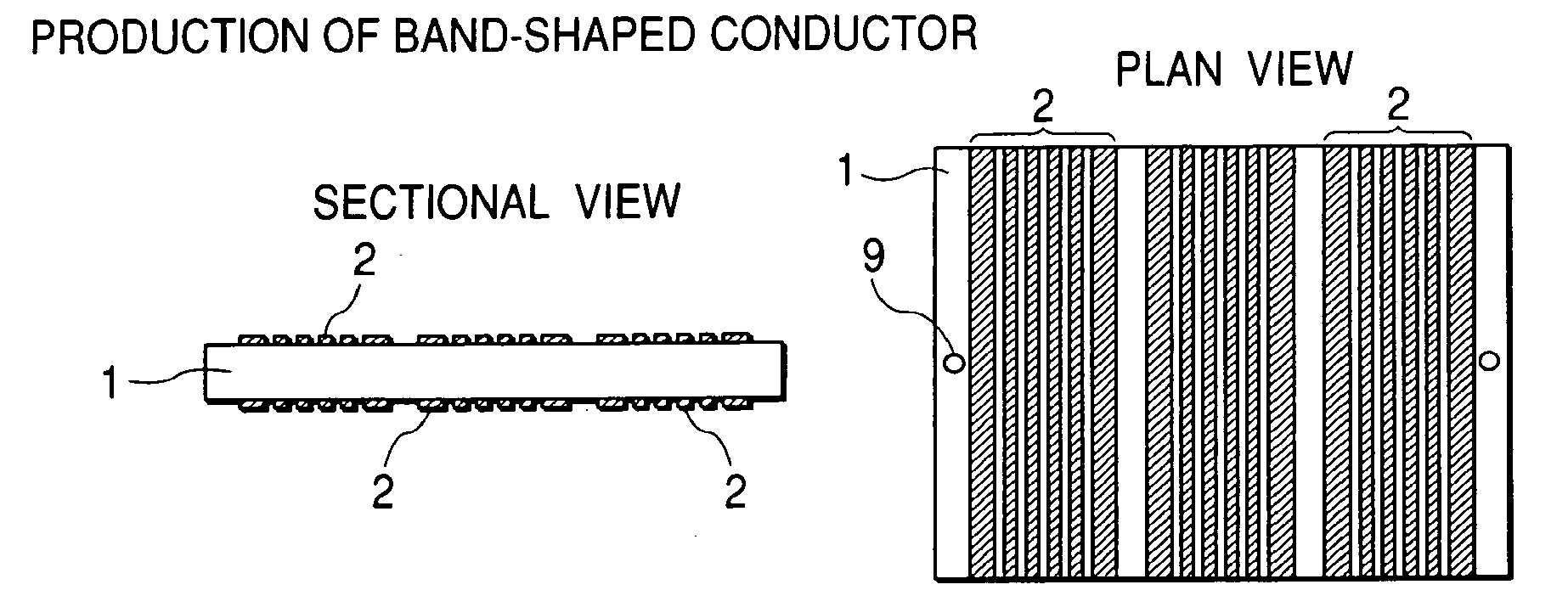
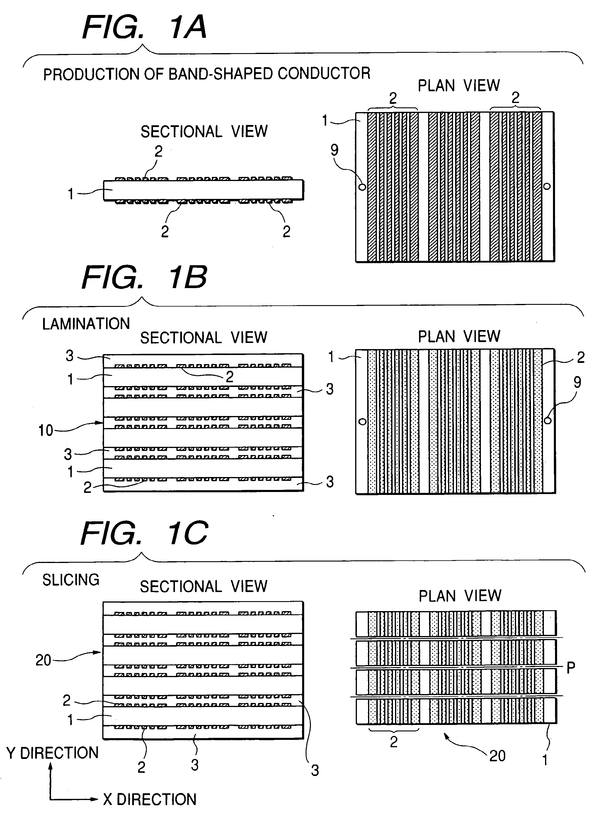
[0026] A first embodiment of the invention will be described with reference to FIGS. 1A to 1C and FIGS. 2A to 2D. First, in the band-shaped conductor production step shown in FIG. 1A, an organic core board 1 having a core material is prepared and a plurality of parallel band-shaped conductor patterns 2 are formed on front and rear surfaces of the board 1 by use of a plurality of front and rear alignment through-holes 9 formed in the board 1.
[0027] The core material-including organic core board 1 is a resin board reinforced with a core material impregnated with a resin. Examples of the core material include glass cloth, resin cloth such as Kepler, and a porous sheet of a fluororesin (trade name: Teflon). Additives may be preferably added to the resin, for example, to control a linear expansion coefficient and improve electrical characteristic. Examples of the additives include spherical silica filler, ferroelectric powder such as barium titanate powder, and ferrite powder (composite...
second embodiment
[0048] A second embodiment of the invention will be described with reference to FIGS. 3A to 3C and FIGS. 4A to 4D. First, in the band-shaped conductor production step shown in FIG. 3A, a core board 1A is prepared and a plurality of parallel band-shaped conductor patterns 2 are formed on a surface of the board 1A.
[0049] A resin board or a resin board reinforced with a core material impregnated with a resin can be used as the core board 1. Examples of the core material include glass cloth, resin cloth such as Kepler, and a porous sheet of a fluororesin (trade name: Teflon). Additives may be preferably added to the resin as a main material, for example, to control a linear expansion coefficient and improve electrical characteristic. Examples of the additives include spherical silica filler, ferroelectric powder such as barium titanate powder, and ferrite powder (composite ferrite). For production of high-frequency parts such as a high-frequency coil, a high-Q low-ε material such as a ...
third embodiment
[0057] A third embodiment of the invention will be described with reference to FIGS. 5A to 5D and FIGS. 6A to 6D. First, in the band-shaped conductor production step shown in FIG. 5A, an organic core board 1 having a core material is prepared and a plurality of parallel band-shaped conductor patterns 2 are formed on front and rear surfaces of the organic core board 1 by use of a plurality of front and rear alignment through-holes 9 formed in the organic core board 1. This step is the same as in the first embodiment.
[0058] Then, in the first lamination step shown in FIG. 5B, interlayer electrically insulating layers (prepregs or adhesive sheets) 4 are put on front and rear surfaces of the organic core board 1 having the parallel band-shaped conductor patterns 2 formed on its front and rear surfaces in the band-shaped conductor production step. The interlayer electrically insulating layers 4 and the organic core board 1 are laminated integrally by pressing, heating, etc. In this mann...
PUM
| Property | Measurement | Unit |
|---|---|---|
| thick | aaaaa | aaaaa |
| height | aaaaa | aaaaa |
| height | aaaaa | aaaaa |
Abstract
Description
Claims
Application Information
 - Generate Ideas
- Intellectual Property
- Life Sciences
- Materials
- Tech Scout
- Unparalleled Data Quality
- Higher Quality Content
- 60% Fewer Hallucinations
Browse by: Latest US Patents, China's latest patents, Technical Efficacy Thesaurus, Application Domain, Technology Topic, Popular Technical Reports.
© 2025 PatSnap. All rights reserved.Legal|Privacy policy|Modern Slavery Act Transparency Statement|Sitemap|About US| Contact US: help@patsnap.com