Digital filter designing method, digital filter designing program, digital filter

Inactive Publication Date: 2005-06-02
NSC CO LTD
View PDF4 Cites 8 Cited by
  • Summary
  • Abstract
  • Description
  • Claims
  • Application Information

AI Technical Summary

Benefits of technology

[0021] As described above, the present invention designs a digital filter by cascade connecting one or more unit filters created from a basic unit filter which uses a predetermined basic numeric string as a filter coefficient. Or the invention also designs a high-pass filter and low-pass filter in such a way that the respective pass bands overlap with each other in the pass band of the unit filter having a relatively wide pass band and designs a digital filter by cascade connecting the unit filter, high-pass filter and low-pass filter. Thus, it is possible to obtain a complicated filter coefficient of the digital filter by substantially only combining unit filters and allow even a non-expert technician to design a filter extremely simply.
[0022] Furthermore, the present invention requires only an extremely small number of taps necessary for the digital filter to be designed and requires only a small number of types of filter coefficients necessary for each tap output, making the structure of the digital filter considerably simple. Therefore, it is possible to drastically reduce the number of circuit elements (multipliers in particular), reduce the circuit scale, reduce power consumption and alleviate the calculation load, etc. Furthermore, since the digital filter designed has an extremely simple structure made up of a repetition of the same pattern of a unit filter, it is possible to reduce man-hours for integration and facilitate the integration into an IC.
[0023] Furthermore, according to another aspect of the present invention, by designing a digital filter by cascade connecting unit filters having a greater number of delays inserted between taps (the number of “0”s inserted between filter coefficients), it is possible to arbitrarily narrow the band width without increasing the number of stages of cascade connected filters and the number of taps.
[0025] Furthermore, according to a still further aspect of the present invention, a high-pass filter and low-pass filter are designed in such a way that the respective pass bands overlap with each other in the pass band of the unit filter having a relatively wide pass band, and the operation of narrowing the band width or operation of widening the band width is performed on one or both of the high-pass filter and low-pass filter, and therefore it is possible to fine-adjust the band width simply.

Problems solved by technology

However, the above described conventional filter designing method requires an expert technician to perform design with an immense amount of time and effort, causing a problem that it is not easy to design an FIR filter having a desired characteristic.
Furthermore, even if it is possible to design an FIR filter having substantially a desired characteristic, the number of taps of the designed filter becomes enormous and the coefficient values become extremely complicated and random values.
For this reason, there is a problem that a large-scale circuit structure (adders, multipliers) is required to realize such a number of taps and coefficient values.
Furthermore, there is also a problem that when the designed FIR filter is actually used, the amount of calculation becomes very large and processing load becomes heavy.

Method used


Image

  • Digital filter designing method, digital filter designing program, digital filter
  • Digital filter designing method, digital filter designing program, digital filter
  • Digital filter designing method, digital filter designing program, digital filter

Examples


Embodiment Construction

[0043] Before explaining an embodiment of the present invention, an overview of Japanese Patent Application No. 2001-400673 (hereinafter referred to as “previous application”) already applied by the present applicant will be explained below. According to this previous application, four types of unit filters L1n, L2n, H1n, H2n are created using four types of basic unit filters F0, F1, F2, F3 which will be explained below so as to make it possible to design an FIR filter having a desired frequency characteristic by only combining these unit filters.

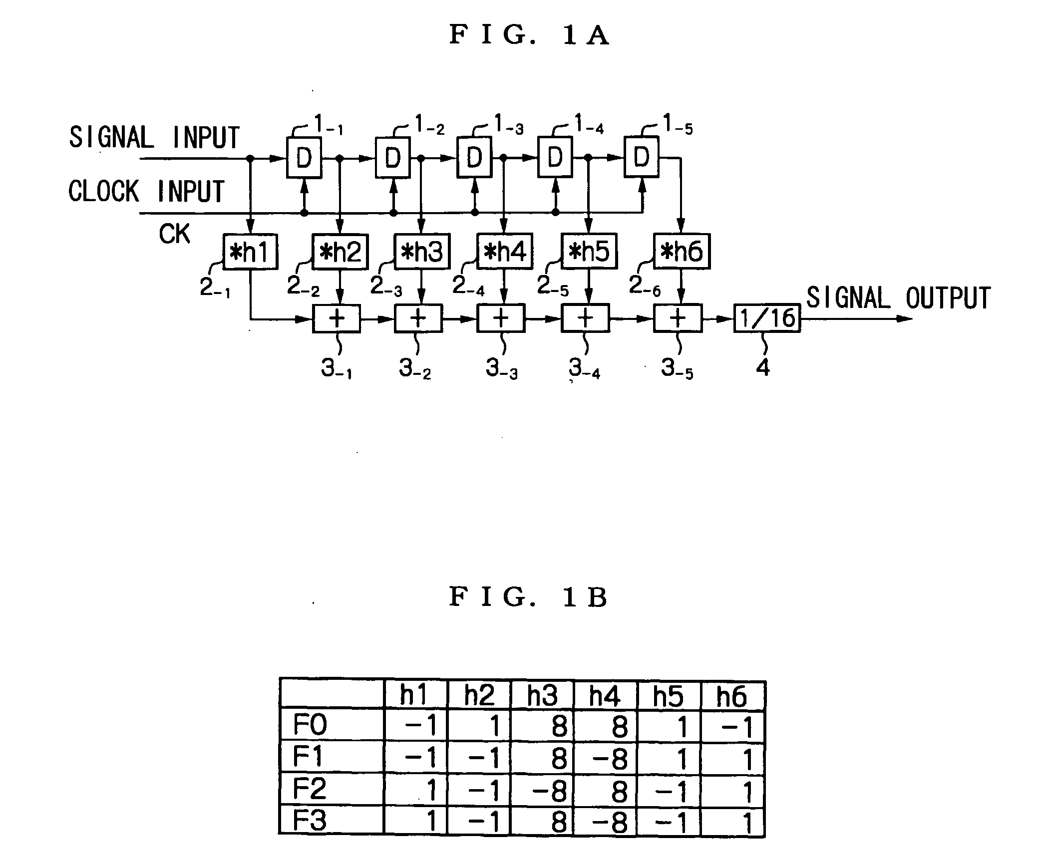
[0044]FIGS. 1A and 1B are diagrams showing the four types of basic unit filters F0 to F3; FIG. 1A shows the circuit structure and FIG. 1B shows numeric strings of filter coefficients. As shown in FIG. 1A, in the basic unit filters F0 to F3, five cascade connected D-type flip flops 1−1 to 1−5 delay an input signal sequentially by 1 clock CK at a time. Then, the signals extracted from the input / output taps of the respective D-type flip flops...


PUM


Abstract

According to a basic unit filter having a predetermined basic numeric string as a filter coefficient, a high-pass unit filter (H15) and a low-pass unit filter (L13) having pass bands having a common center frequency Fc are created. These are connected in the cascade way to design a band pass filter. Characteristic values obtained by combining a few types of unit filters are cancelled by each other. Thus, without pulling out a necessary frequency band and only by the cascade connection of the high-pass unit filter (H15) and the low-pass unit filter (L13), it is possible to extract a superimposed portion as a band pass filter pass band.

Description

BACKGROUND OF THE INVENTION [0001] 1. Field of the Invention [0002] The present invention relates to a digital filter designing method, digital filter designing program and digital filter, and more particularly, to a method of designing an FIR filter, which comprises a tapped delay line made up of a plurality of delayers and performs multiplying signals of the respective taps several-fold and then adding up the results of multiplication and outputting the addition result. [0003] 2. Description of the Related Art [0004] Some kind of digital signal processing is generally performed in various kinds of electronic devices provided in various fields of communication, measurement, sound / image signal processing, medical care, seismology, and so on. One of the most significant basic operation of the digital signal processing is filtering which extracts only a signal having a necessary frequency band from an input signal in which signal and noise are mixed. For this reason, digital filters a...

Claims


Application Information

Patent Timeline
IPC IPC(8): G06F17/10H03H17/02
CPCH03H17/0286
Inventor KOYANAGI, YUKIO
Owner NSC CO LTD
Why Eureka
Try Eureka