
Single chip radio with integrated antenna

a single chip radio and antenna technology, applied in the field of single chip radios, can solve the problems of high assembly cost, increased power consumption, degraded reliability, etc., and achieve the effects of reducing the impact of chip area, reducing interaction, and reducing the loss associated

Inactive Publication Date: 2005-05-26
UNIV OF FLORIDA RES FOUNDATION INC
View PDF15 Cites 53 Cited by
  • Summary
  • Abstract
  • Description
  • Claims
  • Application Information

AI Technical Summary

Benefits of technology

[0024] The radio preferably includes separate transmit and receive antennas. This removes the need for a transmit / receive switch. In this embodiment, the transmit antenna can provide an impedance less than 50 ohms and the receive antenna provides an impedance more than 50 ohms.
[0030] The single chip radio can also be used for ultra-wide-band (UWB) communciations. Such a radio preferably includes an upconverter, such as a mixer. The upconverter frequency translates signals UWB signals to be transmitted to at least 10 GHz, and preferably at least 20 GHz, such as 24 GHz. This embodiment eliminates the need for a wideband antenna by upconverting the signal to higher frequency (e.g. 24 GHz) to make a wideband signal effectively a narrow band signal compared to the carrier.
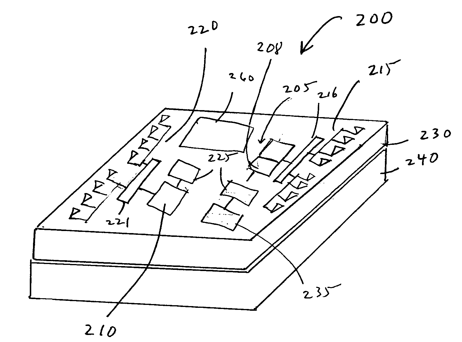
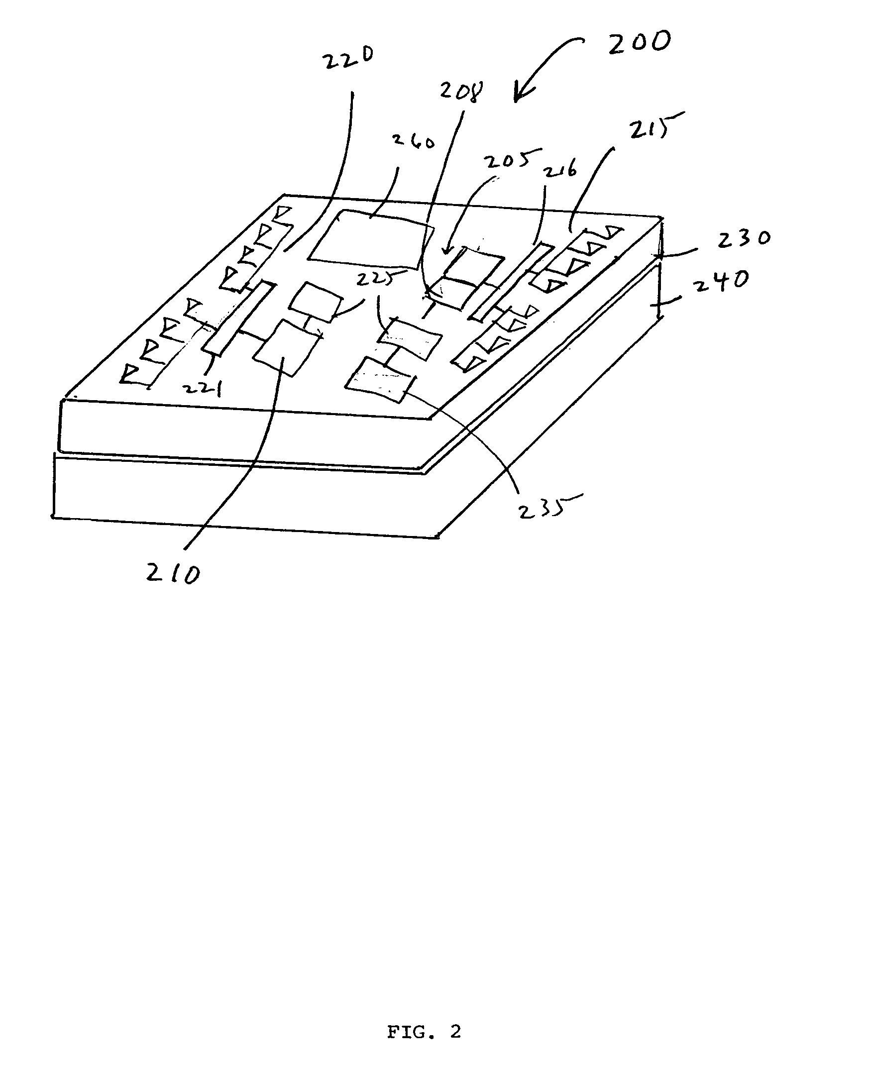
[0031] Antennas are preferably balanced antennas, such as dipole antennas. In another embodiment, the antenna(s) are placed within 2 mm of an edge of the substrate. Placing antennas along the edge reduces loss associated with the silicon substrate, reduces impact on chip area, and in the case of a dipole antenna, reduces interaction among antennas exploiting the null in the radiation pattern along the dipole axis.

Problems solved by technology

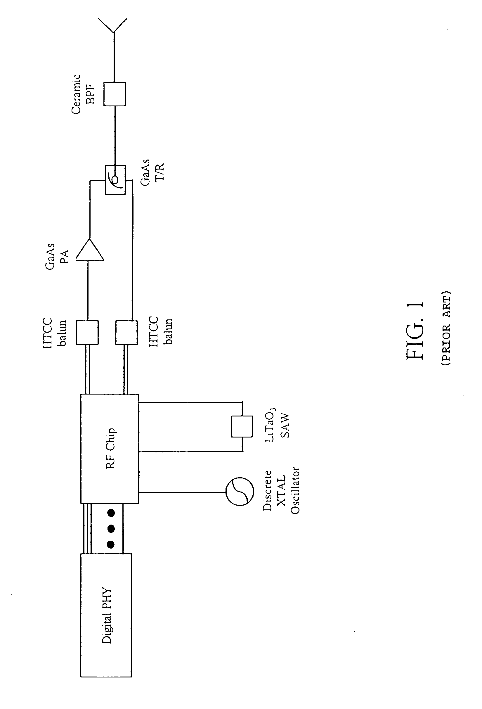
However, hybrids result in high cost due to assembly, degraded reliability and increased power consumption mainly resulting from interconnection of the various circuit components, as compared to a hypothetical single chip radio.
In addition to the above mentioned shortcomings of the hybrid radio approach, the hybrid approach necessarily produces a radio having a large footprint.
The realization of a practical fully integrated single chip radio has not seriously been considered until recently primarily because of the frequency limitations of the transistors combined with the required size of antenna structures to process these frequency limited signals.
Thus, on chip integration of a conventional resonant antenna, such as a half wave or quarter wave antenna, is clearly not practical as the chip would require dimensions of about 62.5, or 31.25 mm, respectively.
However, sufficiently fast transistors, amplifiers and oscillators alone are not sufficient to realize practical single chip radios.
For example, any one the following challenges can limit the performance and prevent practical realization of a true single chip radio: 1.
Substrate noise coupling from digital circuits through the common substrate to the on-chip antennas can also be a problem.
The dielectric surrounding integrated antennas tend to be lossy, such as moderately to heavily doped silicon substrates.
Long leads from a remotely located battery can require large value capacitors, the large value capacitors requiring large areas for implementation.
Although many have referred to fabrication or design of radio subsystems as a “single-chip radio”, such systems lack one or more important components for a true single chip radio, such as on-chip antennas and / or digital circuitry, such as digital signal processors.
However, even the realization of a fully integrated single-chip transceiver has proved elusive.

Method used


Image

  • Single chip radio with integrated antenna
  • Single chip radio with integrated antenna
  • Single chip radio with integrated antenna

Examples


examples

[0095] It should be understood that the examples and embodiments described herein are for illustrative purposes only and that various modifications or changes in light thereof will be suggested to persons skilled in the art and are to be included within the spirit and purview of this application. The invention can take other specific forms without departing from the spirit or essential attributes thereof

[0096]FIG. 4 shows the measured antenna gain (Ga) vs. zigzag antenna axial length on a 20 ohm-cm Si substrate having a 3-μm oxide layer thereon. The separation distance between transmit and receive antennas was 1 meter. As shown by the measurements, the 3-mm zigzag antenna has about 3 and 9 dB higher gain than 2 and 1-mm antennas, respectively, while having only about 1 dB lower gain than the 4-mm antenna. Thus, the 3-mm zigzag dipole antenna is a preferred choice for μNode applications as it fits the μNode size requirement.

[0097]FIG. 5 shows the measured antenna gain vs. substrate...


PUM

PropertyMeasurementUnit
Lengthaaaaaaaaaa
Thicknessaaaaaaaaaa
Thicknessaaaaaaaaaa

Abstract

A true single-chip radio for bidirectional wireless communications includes a bulk substrate, at least one integrated antenna, at least one transceiver, baseband circuitry and at least one filter all integrally formed in or on the substrate. The radio preferably includes a low-loss dielectric propagating layer disposed beneath the substrate to improve antenna gain. The integrated antenna can be an adaptive array for beamforming.

Description

CROSS-REFERENCE TO RELATED APPLICATIONS [0001] This application claims the benefit of U.S. Provisional Application No. 60 / 415,477 entitled “SINGLE CHIP RADIO WITH INTEGRATED ANTENNA” filed Oct. 2, 2002, and U.S. Provisional Application No. 60 / 431,603 entitled “SINGLE CHIP RADIO” filed Dec. 6, 2002, the entireties of both are incorporated herein by reference.STATEMENT REGARDING FEDERALLY SPONSORED RESEARCH OR DEVELOPMENT [0002] The United States Government has certain rights to this invention pursuant to DARPA Contract No. N66001-03-1-8901.FIELD OF THE INVENTION [0003] The invention relates to a single chip radio including a radio transceiver subsystem along with one or more on-chip antennas, baseband processors and filter structures. BACKGROUND [0004] High performance conventional radio designs incorporate optimized individual circuit components which are formed from different manufacturing processes. Among these components are gallium-arsenide-based power amplifiers (PAs) and trans...

Claims


Application Information

Patent Timeline
IPC IPC(8): H01Q1/38H01Q1/52H01Q23/00H04B1/38H04B1/40H04B1/69
CPCH01Q1/38H01Q1/525H01Q23/00H04B1/7163H04B1/3827H04B1/40H04B1/38
Inventor KYONGYOP O, KENNETH
Owner UNIV OF FLORIDA RES FOUNDATION INC
Learn More