Ceramic filter and exhaust gas decontamination unit
- Summary
- Abstract
- Description
- Claims
- Application Information
AI Technical Summary
Benefits of technology
Problems solved by technology
Method used
Image
Examples
example 1
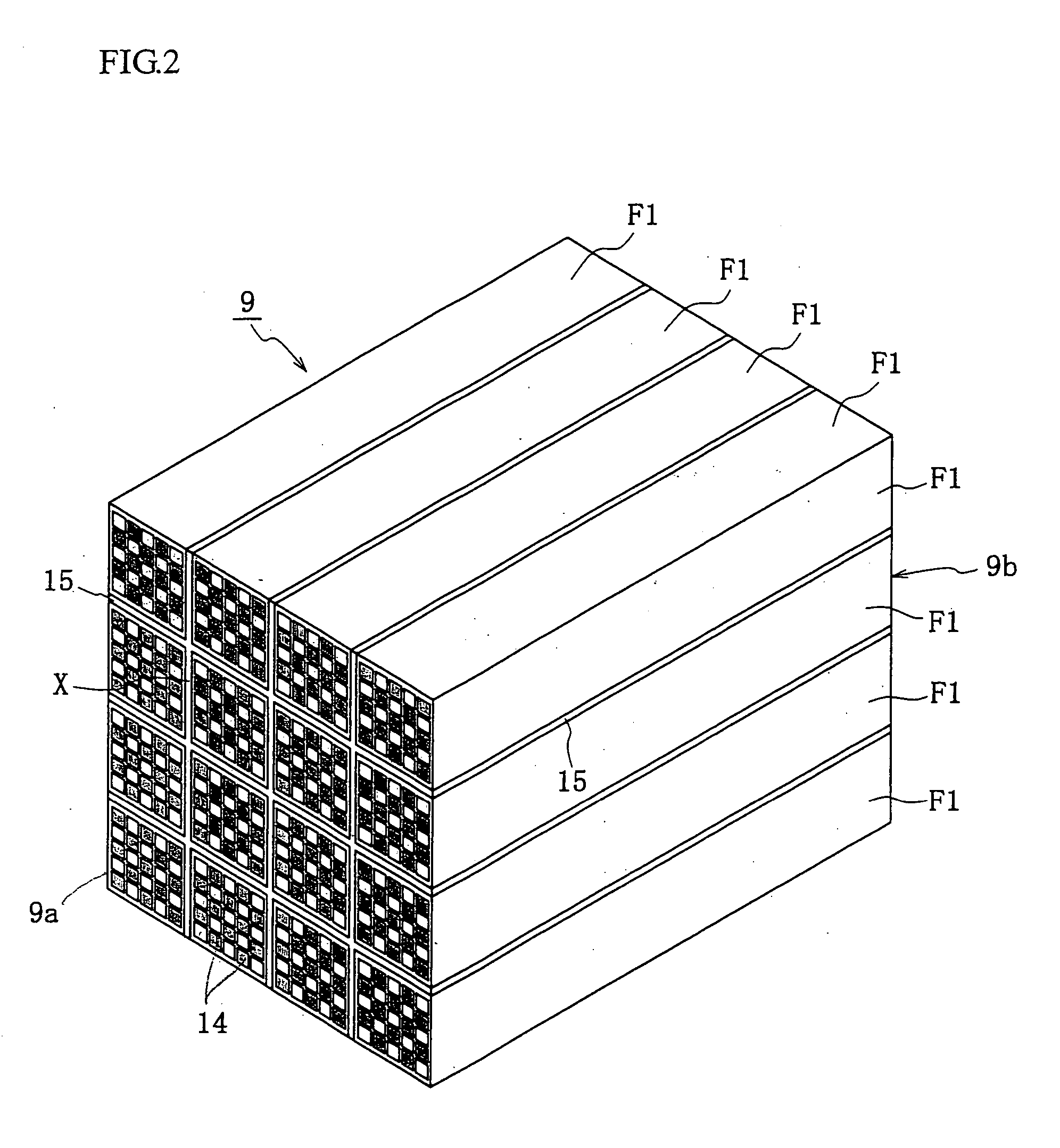
[0177] In Example 1-1, the ceramic filter 9 is basically prepared in the same manner as the reference example. In Example 1-1, however, a ceramic filter 9 of 16 filters in total is prepared by using two kinds of SiC filter and cordierite filter as shown in Table 1 and arranging 12 commercially available cordierite filters in the peripheral portion and 4 SiC filters in the central portion. In this case, the thermal conductivity of cordierite is 2 W / mk, and the thermal conductivity of SiC is 70 W / mk.
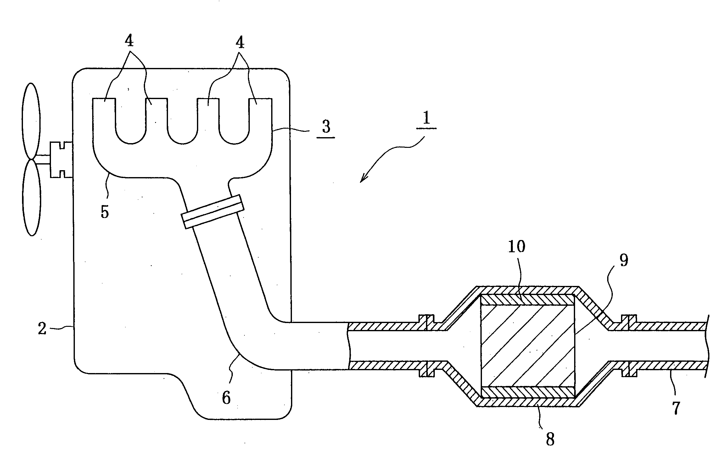
[0178] Then, the thus obtained ceramic filter 9 is wound with a heat insulating material 10 and received in a casing 8 at this state, and then the exhaust gas of the engine is fed for a constant time as shown in the reference example. After the catching for 10 hours, the ceramic filter 9 is taken out and cut to conduct visual observation. As a result, the storing amount at the peripheral portion becomes smaller than that at the central portion as shown in FIG. 6(a).
[0179] Next, a new cer...
example 2
[0183] In this example, experiments are carried out as a typical example of ceramic filters 9 having different pressure losses. The ceramic filter 9 is basically prepared in the same manner as in the reference example. In this case, the filters are prepared by changing molds to adjust a thickness of cell wall 13 in the SiC filter unit or cell number as shown in Table 2 and by changing a compounding ratio of starting materials to adjust a porosity and a pore size as shown in Table 3.
[0184] With respect to the filter units F1, a standard pressure loss is measured (pressure difference is measured when air of PMO g / L is flown at a flow rate of 13 m / s), and the results are also shown in Tables 2 and 3.
[0185] Then, the ceramic filter 9 is prepared by setting 12 filters to the peripheral portion and setting 4 filters to the central portion as shown in Table 4.
[0186] Next, the thus obtained ceramic filter 9 is wound with a heat insulating material 10 and received in a casing 8, and an ex...
example 3
[0190] Even in Example 3-1, the ceramic filter 9 is basically prepared in the same manner as in the reference example. Two kinds of SiC filters having different strengths are used in Example 3-1 as shown in Table 5. In order to change the strength, a higher firing temperature is set to 2300° C.-3 hr, and a lower firing temperature is set to 2100° C.-2 hr. The strength is measured by a three-point bending test described in JIS R1625. In this case, a lower spun is set to 135 mm, and a head speed is set to 0.5 mm / sec. This test is carried out 20 times, and the ceramic filter 9 is prepared by selecting filters from the same production lot. In this case, the ceramic filter 9 is prepared by setting 12 SiC filters having an average bending load of 250 kg / cm2 to the peripheral portion and 4 SiC filters having an average bending load of 350 kg / cm2 to the central portion.
[0191] Then, the thus obtained ceramic filter 9 is wound with a heat insulating material 10 and received in a casing 8, an...
PUM
| Property | Measurement | Unit |
|---|---|---|
| Temperature | aaaaa | aaaaa |
| Fraction | aaaaa | aaaaa |
| Fraction | aaaaa | aaaaa |
Abstract
Description
Claims
Application Information
 - R&D
- Intellectual Property
- Life Sciences
- Materials
- Tech Scout
- Unparalleled Data Quality
- Higher Quality Content
- 60% Fewer Hallucinations
Browse by: Latest US Patents, China's latest patents, Technical Efficacy Thesaurus, Application Domain, Technology Topic, Popular Technical Reports.
© 2025 PatSnap. All rights reserved.Legal|Privacy policy|Modern Slavery Act Transparency Statement|Sitemap|About US| Contact US: help@patsnap.com


