
Power supply apparatus

a technology for power supply equipment and power supply, which is applied in the direction of electric variable regulation, process and machine control, instruments, etc., can solve the problems of becoming an obstacle in miniaturizing and lightening portable equipment, and achieve the effect of reducing mounting area and reducing manufacturing costs

Inactive Publication Date: 2005-03-17
ROHM CO LTD
View PDF6 Cites 19 Cited by
  • Summary
  • Abstract
  • Description
  • Claims
  • Application Information

AI Technical Summary

Benefits of technology

[0016] Any number of the light-emitting elements may be connected in series and it also implies a single light-emitting element, for which a drive voltage is relatively high, as a special case. The low dropout control circuit, which is, for example, a kind of linear regulator, can step down the preliminary boosted voltage in a simple configuration.
[0019] According to the power supply apparatus, a plurality of device drivers such as an LCD driver, an LED driver, or the like can be monolithically integrated so as to share the boosting circuit, and therefore the mounting area can be reduced and manufacturing cost can be held down.

Problems solved by technology

To boost the battery voltage by a charge pump circuit, a large number of capacitors are necessary according to the number of boosting steps, and therefore it becomes a big problem on component mounting especially when there arises a need to develop portable equipment smaller and thin-shaped.
In addition, if boosting circuits are individually provided for the LCD panel and the LED element, which require different drive voltages, for boosting the battery voltage to the respective drive voltages, a mounting area in a power supply IC expands, and therefore it becomes an obstacle in miniaturizing and lightening the portable equipment.

Method used


Image

  • Power supply apparatus
  • Power supply apparatus
  • Power supply apparatus

Examples


Embodiment Construction

[0025] The invention will now be described based on the following embodiments which do not intend to limit the scope of the present invention but exemplify the invention. All of the features and the combinations thereof described in the embodiments are not necessarily essential to the invention.

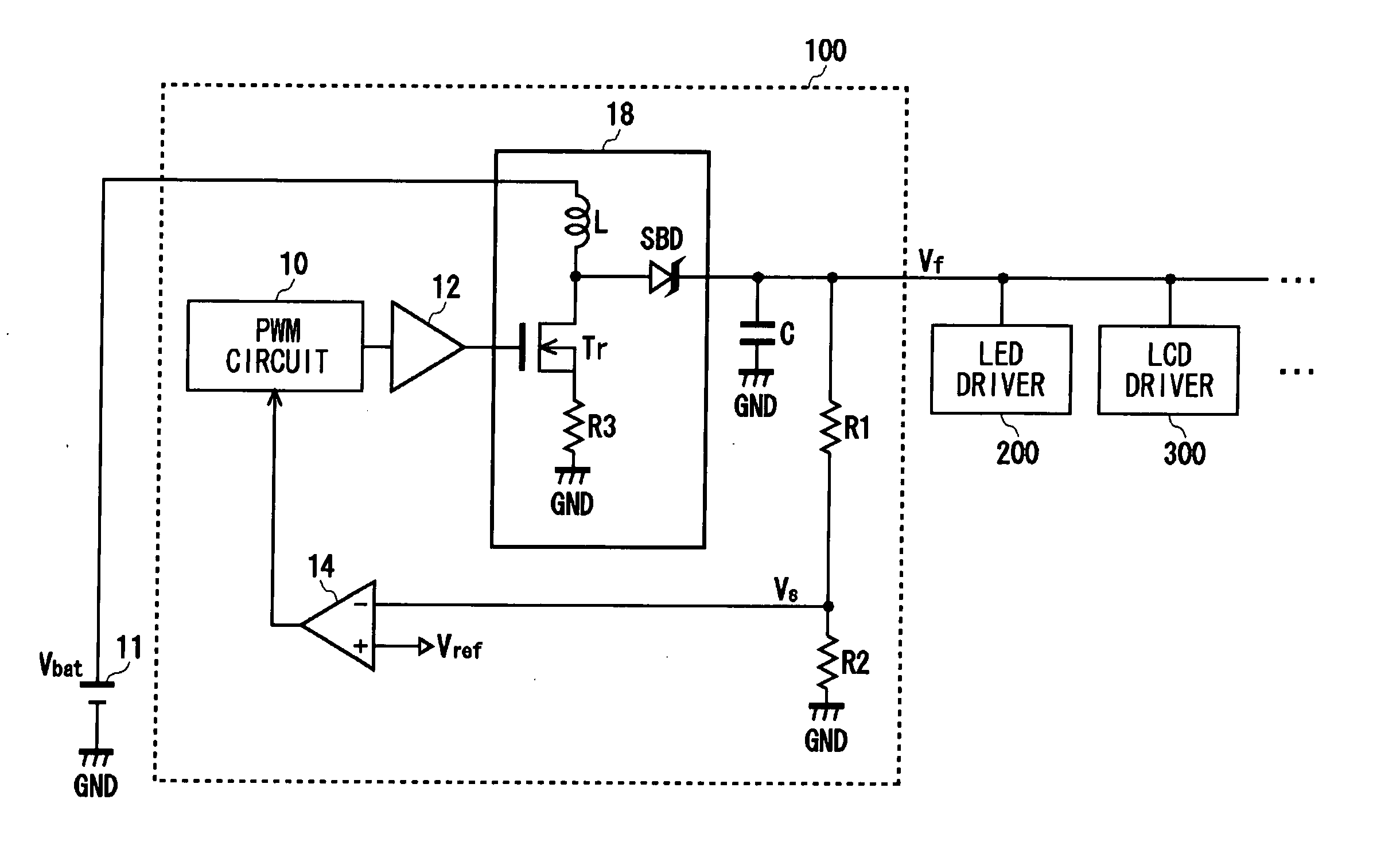
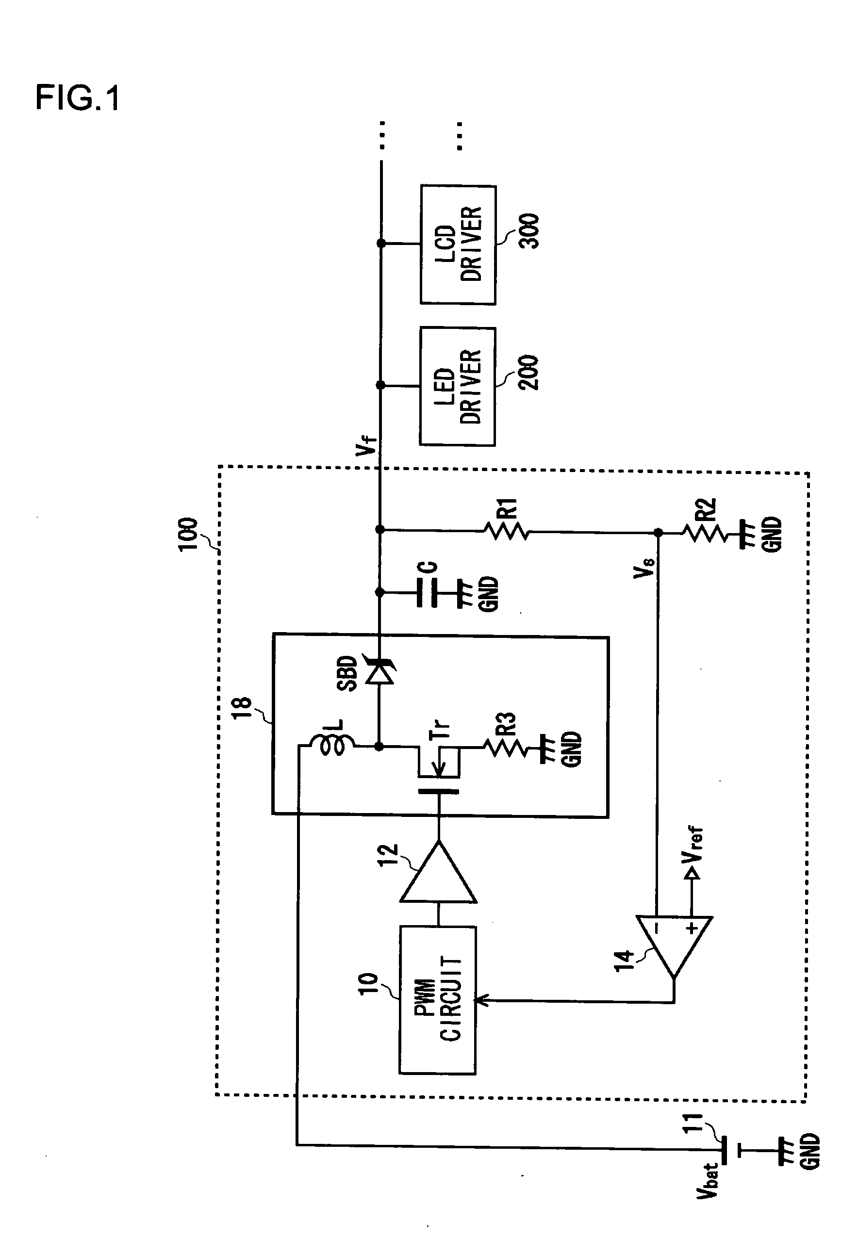
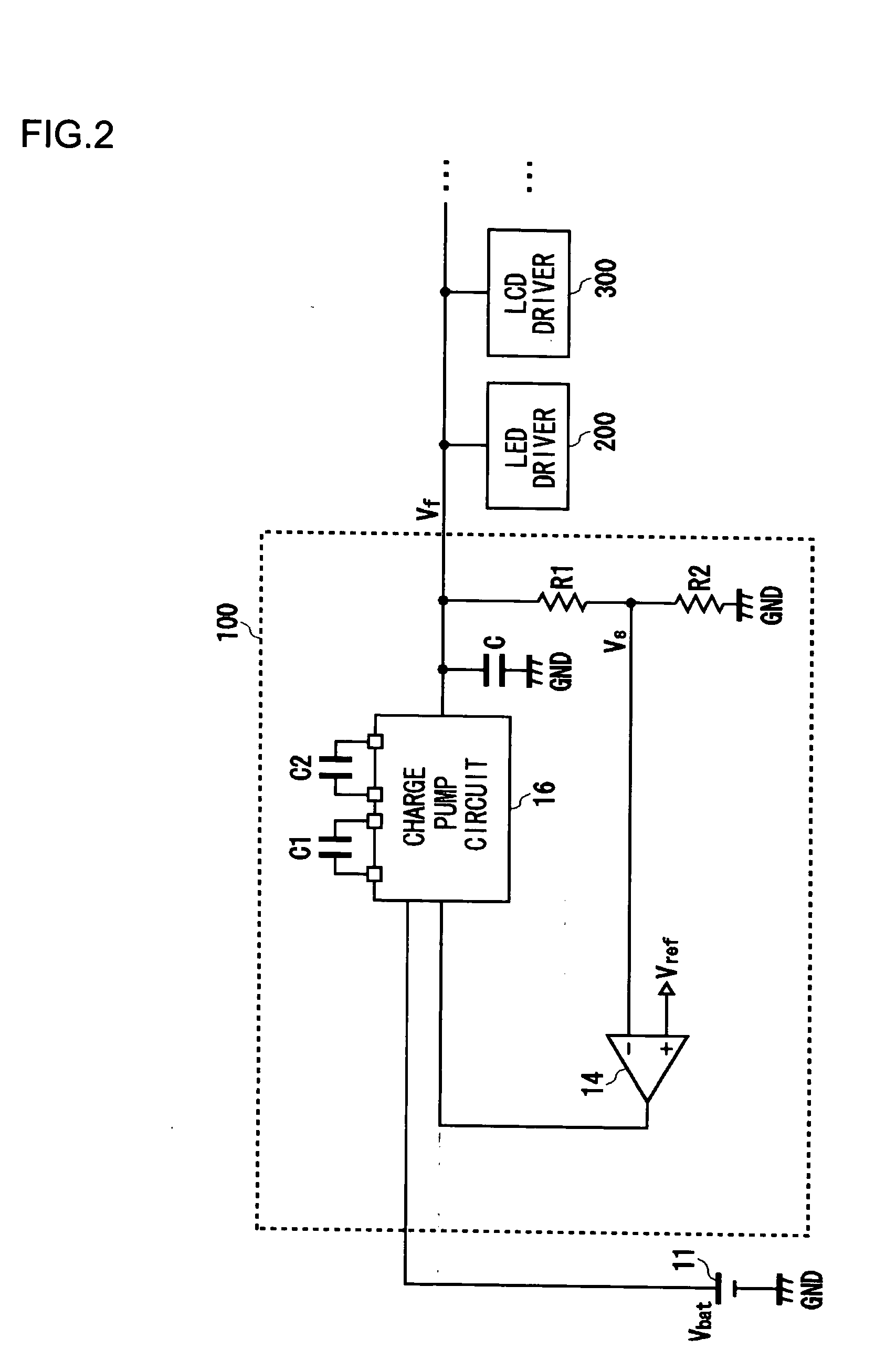
[0026] As a power supply apparatus according to embodiments of the present invention, FIG. 1 and FIG. 2 illustrate different structures of a common boosting converter 100, and FIG. 3 illustrates a structure of an LCD panel module 130 that includes the common boosting converter 100.

[0027]FIG. 1 illustrates a structure of the common boosting converter 100. The common boosting converter 100 receives an input of a battery voltage Vbat from a lithium ion battery 11 and boosts the input voltage in a switching system, and thereby outputs a preliminary boosted voltage Vf. Various types of device drivers such as an LED driver 200, an LCD driver 300 or the like are connected with the common boosting ...


PUM

PropertyMeasurementUnit
voltageaaaaaaaaaa
voltageaaaaaaaaaa
drive voltageaaaaaaaaaa

Abstract

An LCD panel module includes a common boosting converter, an LCD boosting circuit, an LDO control circuit, and constant current circuits for parallel-connected LED elements and series-connected LED elements. The LCD panel module is so configured that a type-switching unit can switch over between Type 1 in which the LED elements are connected in parallel and Type 2 in which the LED elements are connected in series. The common boosting converter preliminarily boosts a battery voltage supplied from a lithium ion battery to a low voltage or a high voltage and supplies the boosted voltage to the parallel-connected LED elements or series-connected LED elements respectively. The LCD boosting circuit boosts the low voltage and supplies it to an LCD panel, while the LDO control circuit steps down the high voltage and supplies it to the LCD panel.

Description

BACKGROUND OF THE INVENTION [0001] 1. Field of the Invention [0002] The present invention relates to a power supply apparatus which supplies device drive voltage by boosting power supply voltage. [0003] 2. Description of the Related Art [0004] To drive an LCD (liquid crystal display) panel for battery-driven portable equipment, such as cellular phones or PDAs (personal digital assistants), it is necessary to supply a drive voltage, which is a battery voltage of about 3.6V supplied from a lithium ion battery or the like boosted to a high voltage of about 15 V. In battery-driven portable equipment, LED (light-emitting diode) elements are used for a variety of purposes, which include use as a backlight for an LCD (liquid crystal display), as a flash for an attached CCD (charge coupled device) camera or as an illumination with the LED elements flashing in different emission colors. Driving the LED element requires a large current of about 20-100 mA but a low drive voltage of about 4.5 V...

Claims


Application Information

Patent Timeline
Patent Type & Authority Applications(United States)
IPC IPC(8): G02F1/133G09G3/36H02M3/07H02M3/155H02M3/156
CPCG09G3/36G09G2330/02H02M2001/0045H02M3/156H02M3/07H02M1/0045G02F1/133
Inventor YAMAMOTO, ISAOITO, TOMOYUKIOTA, TAKAHIRO
Owner ROHM CO LTD
Learn More