Relay, relay unit and electrical junction box

a relay unit and relay technology, applied in the direction of relays, coupling device connections, emergency protective circuit arrangements, etc., to achieve the effect of reducing the mounting area

Inactive Publication Date: 2005-02-17
YAZAKI CORP
View PDF6 Cites 5 Cited by
  • Summary
  • Abstract
  • Description
  • Claims
  • Application Information

AI Technical Summary

Benefits of technology

[0013] With such a structure, since the relay is received in the electrical junction box such that the projected area of the relay to be mounted has a minimum value when the relay is mounted in the electrical junction box in a vertical state. This results in a decreased mounting area in the electrical junction box, with a resultant miniaturization of the electrical junction box.

Problems solved by technology

However, the relay box 120 has no function to enable circuit modifications or circuit alterations and has a function to comply with a single relay circuit, with a resultant troublesome preparation needed for large number of relay boxes 120 specified for particular relay circuits complying with respective vehicle's specifications.

Method used


Image

  • Relay, relay unit and electrical junction box
  • Relay, relay unit and electrical junction box
  • Relay, relay unit and electrical junction box

Examples


Embodiment Construction

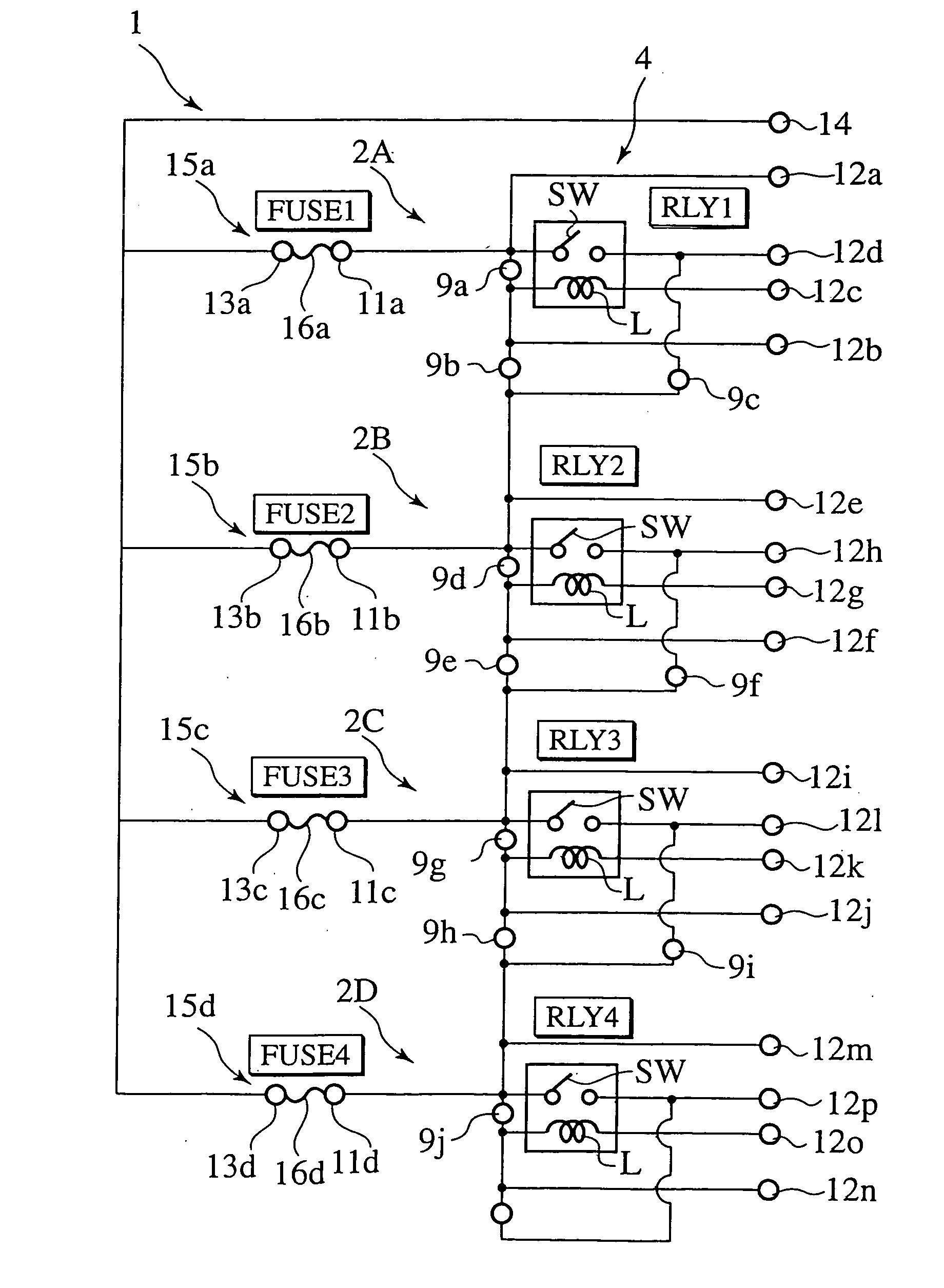
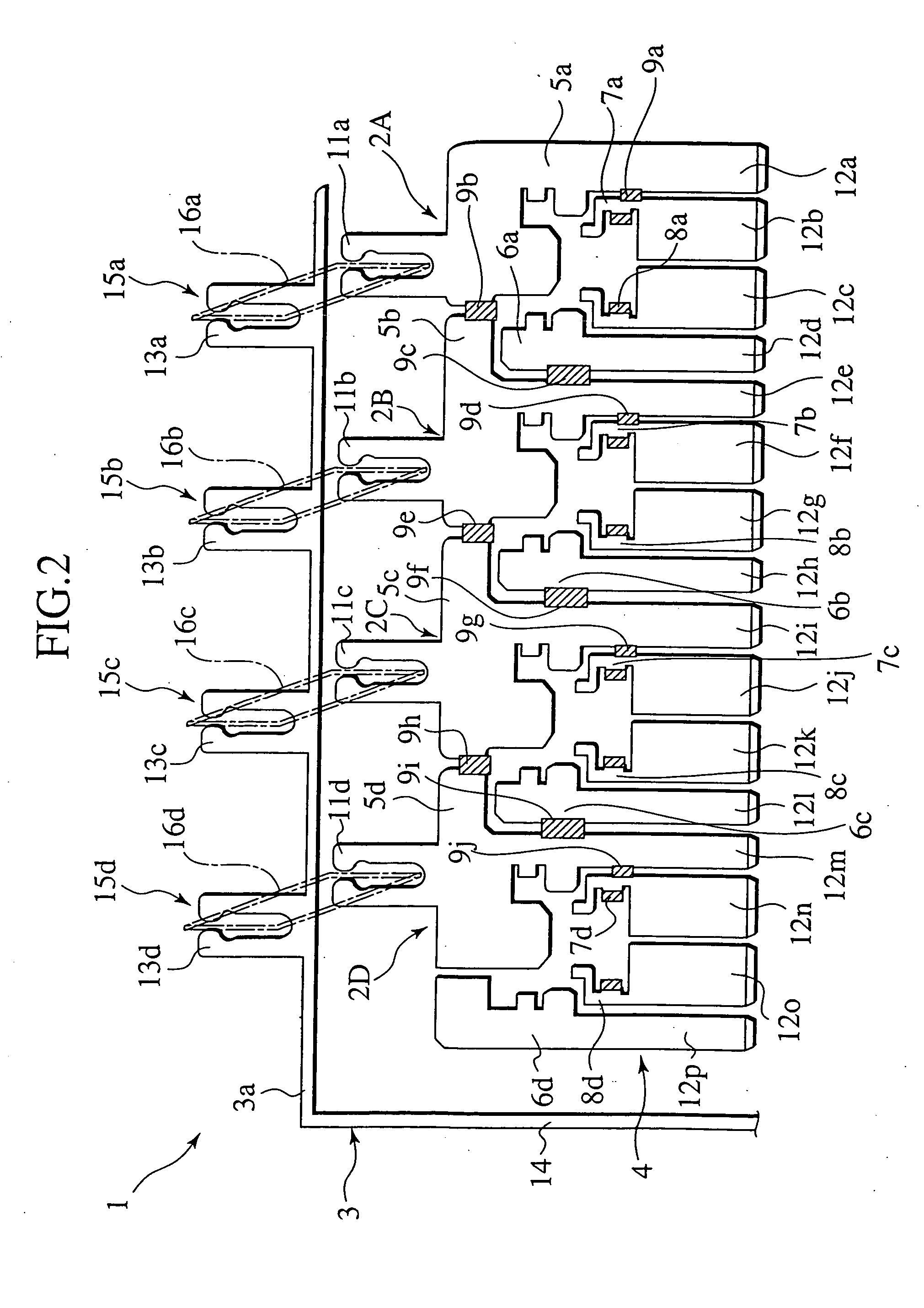
[0031] To describe the present invention more in detail, a relay unit of a first preferred embodiment of the present invention will be explained below with reference to FIGS. 2 to 9, wherein FIG. 2 is a structural view illustrating a basic bus bar circuit body 4 and a power supply bus bar 3 which form a relay unit 1 of the first preferred embodiment, FIG. 3 is a circuit diagram of the relay unit 1 with a plurality of electrically conductive trimmer joint portions 9a to 9j, formed in the basic bus bar circuit body 4, shown in a state prior to trimming operation.

[0032] As shown in FIGS. 2 and 3, the relay unit 1 is comprised of four sets of laterally arrayed relays 2A to 2D which is located in a unit case (not shown) in close proximity relationship to one another in the same horizontal plane, and the power supply bus bar 3 located in an area adjacent to the laterally arrayed relays 2A to 2D. The four sets of relays 2A to 2D include four relay switch element elements SW (see FIG. 3), ...


PUM


Abstract

A relay, a relay unit and an electrical junction box are disclosed as including a plurality of relays (22D), each of which includes a pair of switch connector circuit components (5a˜5d, 6a˜6d) between which a relay switch (SW) is intervened, a pair of coil connector circuit components (7a˜7d, 8a˜8d) between which a relay coil (L) is intervened, and a plurality of electrically conductive trimmer joint portions (9a˜9j) joined between the respective switch connector circuit components (5a˜5d, 6a˜6d) and the respective coil connector circuit components (7a˜7d, 8a˜8d) and able to be cut out at suitable cutting points to provide a desired mounting circuit profiled in a selected relay circuit pattern.

Description

BACKGROUND OF THE INVENTION [0001] The present invention relates to a relay unit having a plurality of relays, and a relay to be applied to such a relay unit, and an electrical junction box in which such a relay unit is mounted. [0002] A relay box, which serves as an electrical junction box which an attempt has heretofore been made to be improved, is disclosed in FIG. 1. [0003] In FIG. 1, the relay box 120 is comprised of a relay cavity 121, a fuse cavity 122, a FL cavity 123 and a bus bar 124, with respective cavities 121, 122, 123 receiving electronic component parts such as a relay, a fuse and a FL. The bus bar 124 provides an electrical connection for the respective cavities 121, 122, 123. Further, the respective cavities 121, 122, 123 are inserted with pressure connection terminals, each coupled to an electric wiring through a pressure connection, through which desired electric signals are inputted or outputted. With such a structure, the relay box 120 is formed with a desired ...

Claims


Application Information

Patent Timeline
Patent Type & Authority Applications(United States)
IPC IPC(8): H01H9/10H02G3/16H01H11/00H01R9/22H01R29/00H05K7/02
CPCH01H9/10H01H11/0056H01R29/00H05K7/026H01R9/226H01H2085/208
Inventor NAKAMURA, TSUYOSHIMATSUMURA, HIROYOIWATA, YOSHIFUMI
Owner YAZAKI CORP
Why Eureka
Try Eureka