
Stainless steel plate, method of manufacturing the same, and rubber-coated stainless steel plate gasket

a technology of stainless steel plate and gasket, which is applied in the direction of superimposed coating process, machines/engines, mechanical equipment, etc., can solve the problems of poor adhesion of the stainless steel plate to the adhesive, deterioration of the bonding durability of the rubber layer, and poor adhesion of the stainless steel plate to the heat-resistant rubber, so as to achieve good adhesion to the rubber layer and efficient production

Inactive Publication Date: 2005-03-17
NIPPON KINZOKU CO LTD +1
View PDF3 Cites 16 Cited by
  • Summary
  • Abstract
  • Description
  • Claims
  • Application Information

AI Technical Summary

Benefits of technology

[0011] The present invention is designed to solve the existing technical problems found in the prior art (Patent Documents 1, 2, and 3). It is thus an object of the present invention to provide a gasket core material made of a rubber-coated stainless steel plate with good adhesion to the rubber layer, without using environmentally harmful hexavalent chrome, and by using a technology that makes efficient production possible.

Problems solved by technology

However, due to environmental problems, in place of asbestos, “gaskets made of rubber-coated stainless steel plates” are widely used.
However, adhesion of the stainless steel plate to the heat-resistant rubber, that is, adhesion of the surface of the stainless steel plate to the adhesive, is not good.
This is a particular problem for an engine gasket for a motor vehicle because engine cooling water (antifreeze solution) penetrates the end face of the gasket to which the bonding portion of the rubber layer and the stainless steel plate is exposed due to being repeatedly struck, thereby deteriorating the bonding durability of the rubber layer.
In addition, these methods do not produce sludge.
Furthermore, the hexavalent chrome may be eluted from the gasket of a scrapped car by rainfall, etc., thereby causing soil pollution.
On the other hand, the method of mechanically roughening dull-roll rolling wherein unevenness formed on a rolling roll is transferred to the surface of the stainless steel plate is unsatisfactory, because it is difficult to obtain a sufficiently high anchor effect to hold the rubber layer to the roughened surface.
However, processing cut-out steel powder decreases work efficiency.
In addition, thin steel plates commonly used as the gasket core material are easily bent.
Therefore, these roughening methods are not suitable for the gasket core material.
Furthermore, the method disclosed in Patent Document 3 suffers from the disadvantage of having a very low production efficiency.
The problem is that the alkaline electrolyte is depleted by the electrolytic treatment so after several hours of using the solution, a coating film with good adhesion to rubber cannot be obtained and the solution must be replaced.

Method used


Image

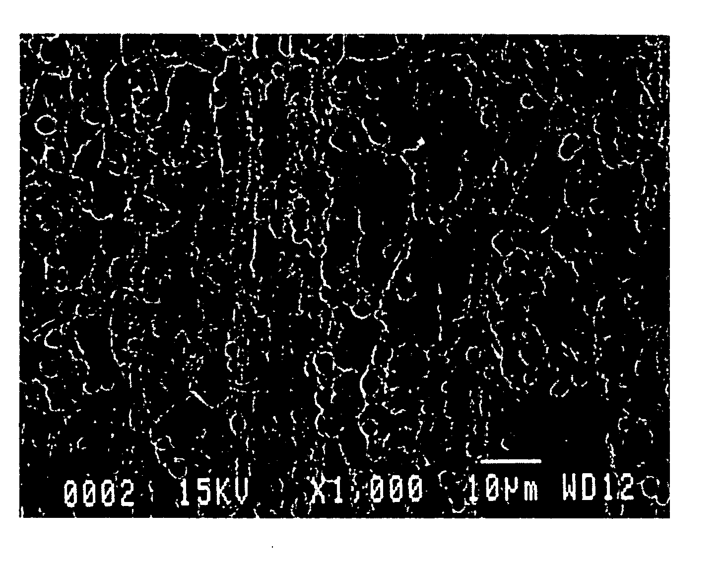
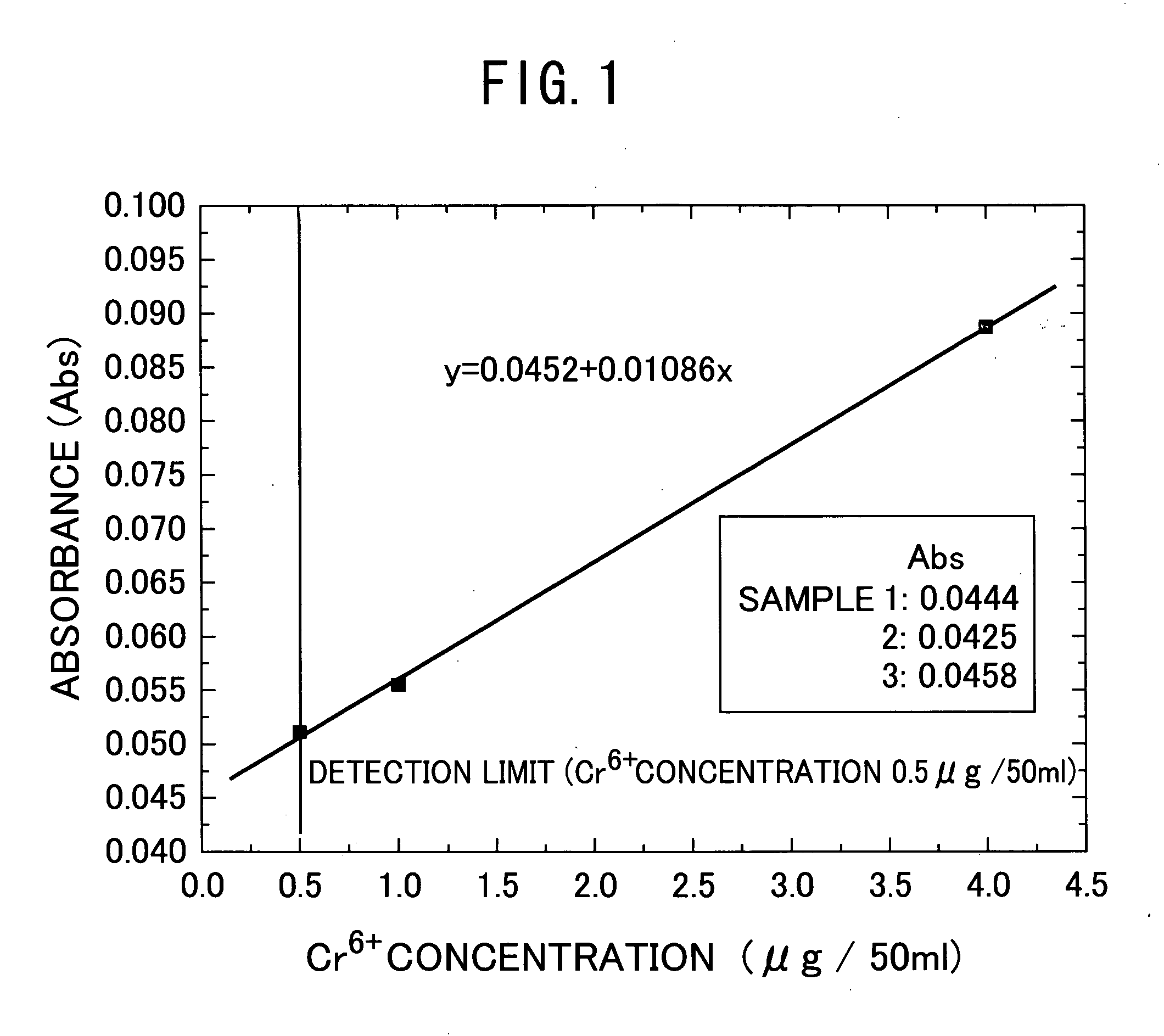
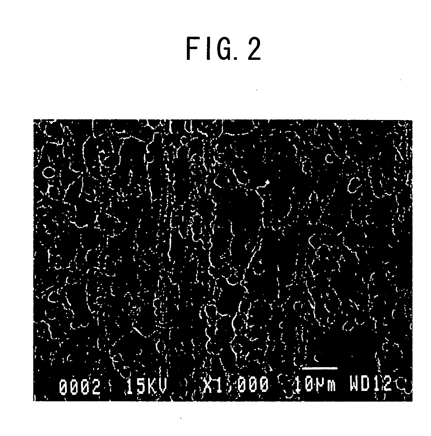
  • Stainless steel plate, method of manufacturing the same, and rubber-coated stainless steel plate gasket
  • Stainless steel plate, method of manufacturing the same, and rubber-coated stainless steel plate gasket
  • Stainless steel plate, method of manufacturing the same, and rubber-coated stainless steel plate gasket

Examples


example 1

[0043] A conventional alkaline electrolytic degreasing was performed on a SUS301, 3 / 4H austenitic stainless steel plate (Hv about 380) with a thickness of 0.3 mm, and then it was washed with water. Next, the stainless steel plate was immersed in a solution of 42 mass % of ferric chloride at 25° C. for one minute to roughen the surface. After washing with water, the stainless steel plate was subjected to cathode electrolysis in an alkaline solution using a mixed solution of 20 g / l of sodium hydroxide, 30 g / l of trisodium phosphate·12 H2O, and 40 g / l of sodium carbonate at 80° C. and the cathode current density of 6 A / dm2, for the process times of 1.5, 2.0, 2.5, 3.0, 5.0, and 10.0 minutes. Then, the stainless steel plate was again washed with water and air dried.

[0044] In addition, for the purpose of comparison, the following sample materials were prepared: a sample material subjected to the coat-type chromate treatment (conventional alkaline degreasing followed by washing with water...

example 2

[0049] A stainless steel plate (Hv about 380) with a multiphase structure of ferrite and martensite was obtained by cold-rolling SUS410S (13Cr—0.08C) to a thickness of 0.3 mm and regulating the metal structure with continuous annealing heat treatment. This stainless steel plate was subjected to the conventional alkaline electrolytic degreasing, followed by washing with water, and the immersion in a solution of 42 mass % of ferric chloride at 25° C. for one minute, thereby roughening the surface. After water washing, the stainless steel plate was subjected to cathode electrolysis in the mixed solution of 20 g / l of sodium hydroxide, 30 g / l of trisodium phosphate·12 H2O, and 40 g / l of sodium carbonate at the solution temperature of 80° C. and the cathode current density of 6 A / dm2, for the treatment times of 1.5, 2.0, 2.5, 3.0, and 10.0 minutes. Then the stainless steel plate was again washed with water and air dried. An adhesive layer containing primarily epoxy resin (with a thickness...


PUM

PropertyMeasurementUnit
Lengthaaaaaaaaaa
Thicknessaaaaaaaaaa
Diameteraaaaaaaaaa

Abstract

This invention provides a rubber-coated stainless steel plate suitable as a gasket core material with excellent adhesion to the rubber layer, a method of manufacturing the same, and a gasket comprising the rubber-coated stainless steel plate. The following are provided by the present invention: a stainless steel plate having a roughened surface on which chrome hydroxide, chrome oxide, iron hydroxide, and iron oxide are deposited; a rubber-coated stainless steel plate formed by coating the surface of the stainless steel plate with a rubber layer; a gasket comprising the rubber-coated stainless steel plate; and a method of manufacturing the stainless steel plate, wherein the stainless steel plate is roughened with at least one of chemical roughening and electrochemical roughening and is then subjected to cathode electrolytic treatment in an alkaline solution.

Description

FIELD OF THE INVENTION [0001] The present invention relates to a gasket core material made of a rubber-coated stainless steel plate, which is used for an engine part of a motor vehicle, etc., a method of manufacturing the gasket core material, and a gasket using the core material. BACKGROUND ART [0002] Conventionally, gaskets used in engines of motor vehicles were made mainly of asbestos. However, due to environmental problems, in place of asbestos, “gaskets made of rubber-coated stainless steel plates” are widely used. These gaskets are created by applying adhesive to the surface of a stainless steel plate used as a core material and then forming a heat-resistant rubber layer such as fluorocarbon rubber, or NBR rubber thereon. However, adhesion of the stainless steel plate to the heat-resistant rubber, that is, adhesion of the surface of the stainless steel plate to the adhesive, is not good. This is a particular problem for an engine gasket for a motor vehicle because engine cooli...

Claims


Application Information

Patent Timeline
IPC IPC(8): C23C28/00B32B15/08C23F1/14C25D9/10C25D11/36C25F3/06F16J15/12
CPCC23C28/00C23F1/14F16J15/122C25F3/06C25D9/10
Inventor YAMAZAKI, OSAMUYASHIRO, TOSHIYUKINUMAZAWA, NOBUHIROOSADA, EIICHIOKAMOTO, MASARUTAKAHASHI, KAZUHIROYOKOTA, RITSUKOFUKAWA, HIROFUMI
Owner NIPPON KINZOKU CO LTD
Learn More