Gas temperature control for a plasma process
- Summary
- Abstract
- Description
- Claims
- Application Information
AI Technical Summary
Benefits of technology
Problems solved by technology
Method used
Image
Examples
embodiment 100
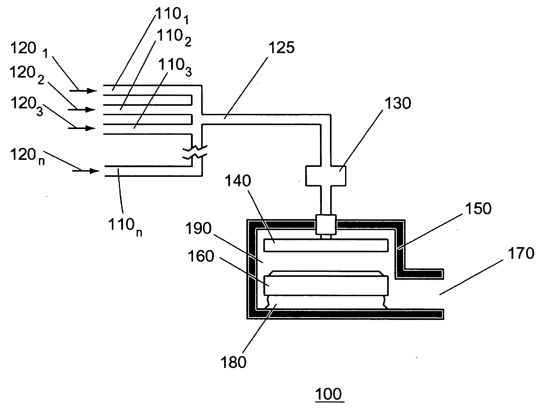
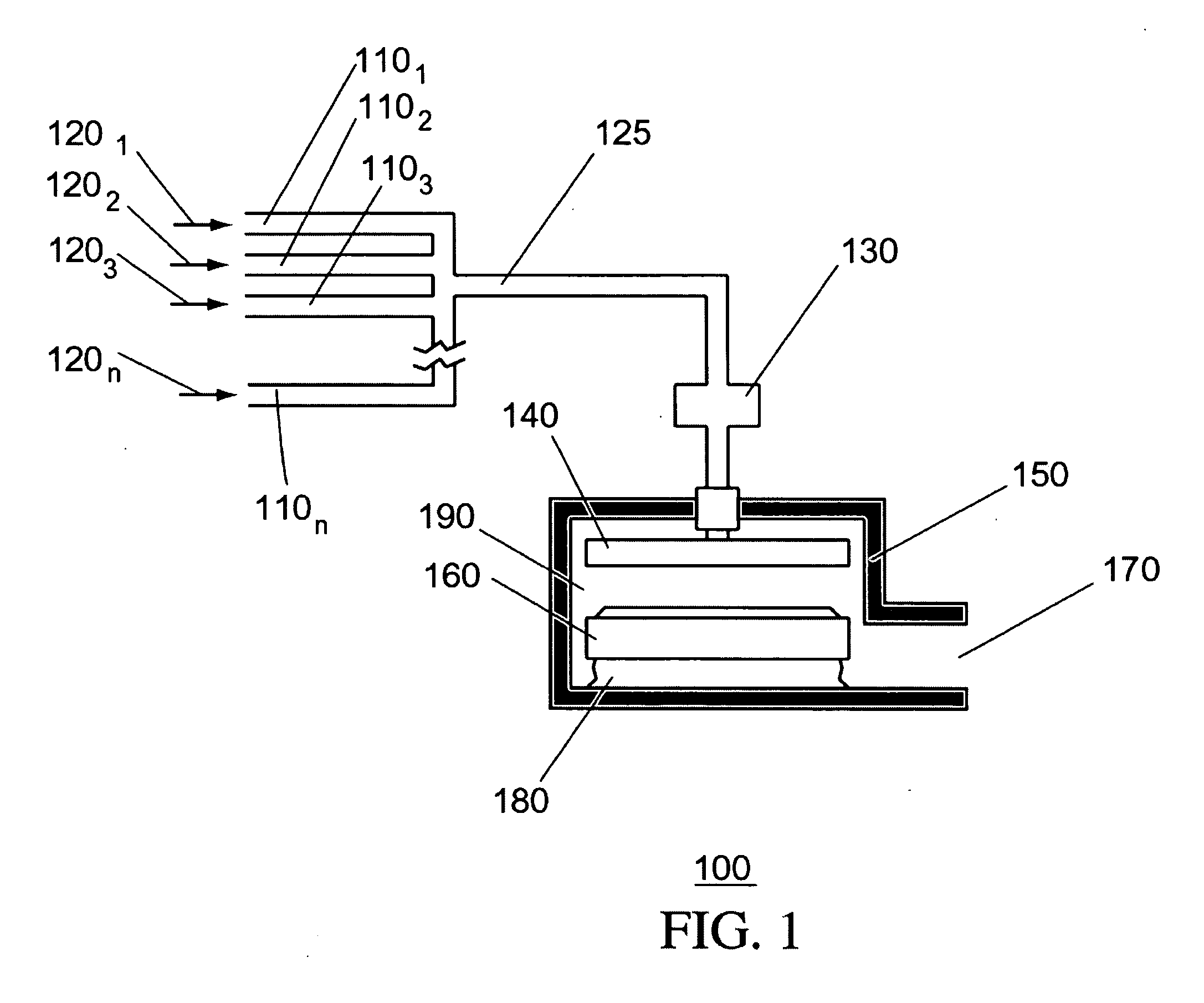
[0024] Referring now to the drawings, wherein like reference numerals designate identical or corresponding parts throughout the several views, FIG. 1 shows a first gas temperature-control embodiment 100 that includes first gas line 1101, second gas line 1102, third gas line 1103, and nth gas line 110n, temperature controller (T / C) 130, process chamber 190 (e.g., a conventional plasma-etching chamber), showerhead 140, chamber wall 150, chuck 160, pump port 170, and bellows 180.
[0025] Gases 1201, through 1202, are gases used to process wafers. Examples of such gases include HBr, SF6 or Cl2 diluted with Ar for silicon etch; C4F8, C5F8 or CF4 diluted with Ar for oxide (e.g., SiO2 etch); SiH4 or SiCl2H2, and CO2 and H2O, or N2O for oxide (e.g., SiO2) deposition; Si(OC2H5) for oxide deposition; BCl3, Cl2, SF6, CF4, CFCl3, CF2Cl2, CF3Cl, CHF3 or C2ClF5 for metal etch; NH3, N2, AsH3, B2H6, KCl PH3, WF6 and SiH4 for chemical vapor deposition (CVD) applications; or O2 for ashing (resist remov...
embodiment 200
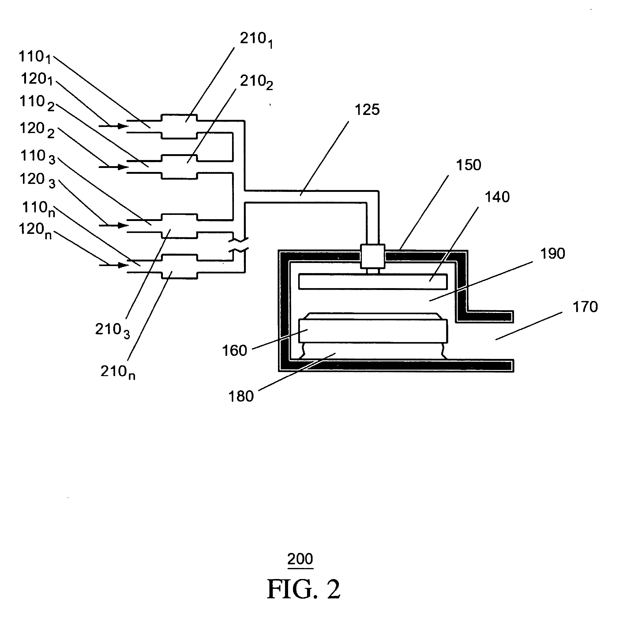
[0034]FIG. 2 shows a second gas temperature-control embodiment 200 that includes a neck 125, process chamber 190, chamber wall 150, showerhead 140, chuck 160, bellows 180, and pump port 170, as in FIG. 1, and are not further described. However, the single T / C 130 has been replaced by dedicated species temperature controllers (T / C 2101 through T / C 210n) for each of the gas lines 1101 through 110n. T / C 2101 through 210n are temperature controllers that separately control the temperature of individual gases, and are explained in further detail in FIGS. 5 and 6.
[0035] In operation, for each i in 1≦i≦n, gas 120i enters its corresponding gas line 110i and passes through T / C 210i, which heats gas 120i to a predetermined temperature Ti. The species of gases continue through their respective gas lines, combine at neck 125, and proceed further to process chamber 190.
[0036]FIG. 3 shows a third gas temperature-control embodiment 300 that, like FIG. 1, includes gas lines 1101 through 110n, neck...
first embodiment
[0043] A first embodiment for heater 585 is an electrical resistance heater wherein heating element 530 comprises a helical coil (or strip) fabricated from a material of high resistivity. Such resistance heaters have typically employed heating elements of a nickel-chromium alloy (nichrome) or an aluminum-iron alloy, which are electrically resistive and which generate heat when an electrical current is applied through the elements. Examples of commercially available materials commonly used to fabricate resistive heating elements employed in ovens are Kanthal, Nikrothal and Alkrothal, which are registered trademark names for metal alloys produced by Kanthal Corporation of Bethel, Conn. The Kanthal family includes ferritic alloys (FeCrAl) and the Nikrothal family includes austenitic alloys (NiCr, NiCrFe). Additional materials include tungsten or platinum. Furthermore, heater unit 585 can comprise a DC or AC power supply capable of delivering a current to the resistive heater element 53...
PUM
| Property | Measurement | Unit |
|---|---|---|
| Temperature | aaaaa | aaaaa |
Abstract
Description
Claims
Application Information
 - R&D
- Intellectual Property
- Life Sciences
- Materials
- Tech Scout
- Unparalleled Data Quality
- Higher Quality Content
- 60% Fewer Hallucinations
Browse by: Latest US Patents, China's latest patents, Technical Efficacy Thesaurus, Application Domain, Technology Topic, Popular Technical Reports.
© 2025 PatSnap. All rights reserved.Legal|Privacy policy|Modern Slavery Act Transparency Statement|Sitemap|About US| Contact US: help@patsnap.com


