
Solid oxide fuel cell, solid oxide fuel cell assembly, solid oxide fuel cell module, and solid oxide fuel cell power generator

a fuel cell and fuel cell technology, applied in the field of solid oxide fuel cells, can solve the problems of power collection loss, easy cracking or peeling of the electrolytic layer, and difficult formation of the interconnector layer b>58/b> itself, and achieve the effect of high start-up performan

Inactive Publication Date: 2005-01-13
SANYO ELECTRIC CO LTD
View PDF2 Cites 69 Cited by
  • Summary
  • Abstract
  • Description
  • Claims
  • Application Information

AI Technical Summary

Benefits of technology

[0007] The present invention has been made with the foregoing problems in mind, and a cylindrical porous metal substrate of low power collection losses is constituted by defining an ideal shape and conductivity thereof. Additionally, an object is to provide an SOFC which secures a high output or exhibits high start-up performance by defining an assembly structure of the SOFC that uses the cylindrical porous metal substrate.
[0010] According to the invention of claim 1, the solid electrolytic layer and the second electrode are formed on the full periphery without disposing any interconnector layers different from the conventional case. Thus, cell formation becomes easy, and it is possible to prevent a problem of occurrence of cracking or peeling-off in the solid electrolytic layer or the second electrode near the interconnector layer.
[0011] Additionally, in the solid oxide fuel cell configured to collect power from the interconnector layer, the structure is complex when the plurality of cells are formed into a module. However, it is possible to facilitate module formation by disposing the collector connected to at least a part of the porous metal substrate.
[0017] According to the invention of claim 4, the plurality of solid oxide fuel cell portions can be easily assembled, and the solid oxide fuel cell assembly having an optional output can be formed.
[0019] According to the invention of claim 5, since the second power collecting section is disposed to be brought into contact with the second electrode of each solid oxide fuel cell portion arranged on the circumference, power collection can be efficiently executed from the second electrode.
[0023] According to the invention of claim 7, since the fuel gas that has not contributed to power generation at the fuel electrode flows out from the porous metal casing into the combustion chamber to be combusted, heat is supplied through the porous metal casing to the solid oxide fuel cell to enable an increase of a temperature to a running temperature zone of the solid oxide fuel cell within a short time. Thus, it is possible to obtain a solid oxide fuel cell power generator of high start-up performance.

Problems solved by technology

However, in the SOFC 50 configured to collect power from the interconnector layer 58, when a plurality of cells 50 are formed into a module, a structure becomes complex, formation of the interconnector layer 58 itself is difficult, and there are problems of easy occurrence of cracking or peeling-off in the electrolytic layer 54 or the fuel electrode 56 near the interconnector layer 58.
However, even in the SOFC that uses the cylindrical porous metal substrate, there are power collection losses caused by internal resistance of the cylindrical porous metal substrate.
Simple setting of a large length of the substrate to secure a current density causes an increase in power collection loses and deterioration of efficiency of the SOFC.
Furthermore, no proposals have been made regarding a method which can increase a temperature of the SOFC run at a high temperature to a running state by a simple structure and within a short time.

Method used


Image

  • Solid oxide fuel cell, solid oxide fuel cell assembly, solid oxide fuel cell module, and solid oxide fuel cell power generator
  • Solid oxide fuel cell, solid oxide fuel cell assembly, solid oxide fuel cell module, and solid oxide fuel cell power generator
  • Solid oxide fuel cell, solid oxide fuel cell assembly, solid oxide fuel cell module, and solid oxide fuel cell power generator

Examples


embodiment 1

[0048] Embodiment 1

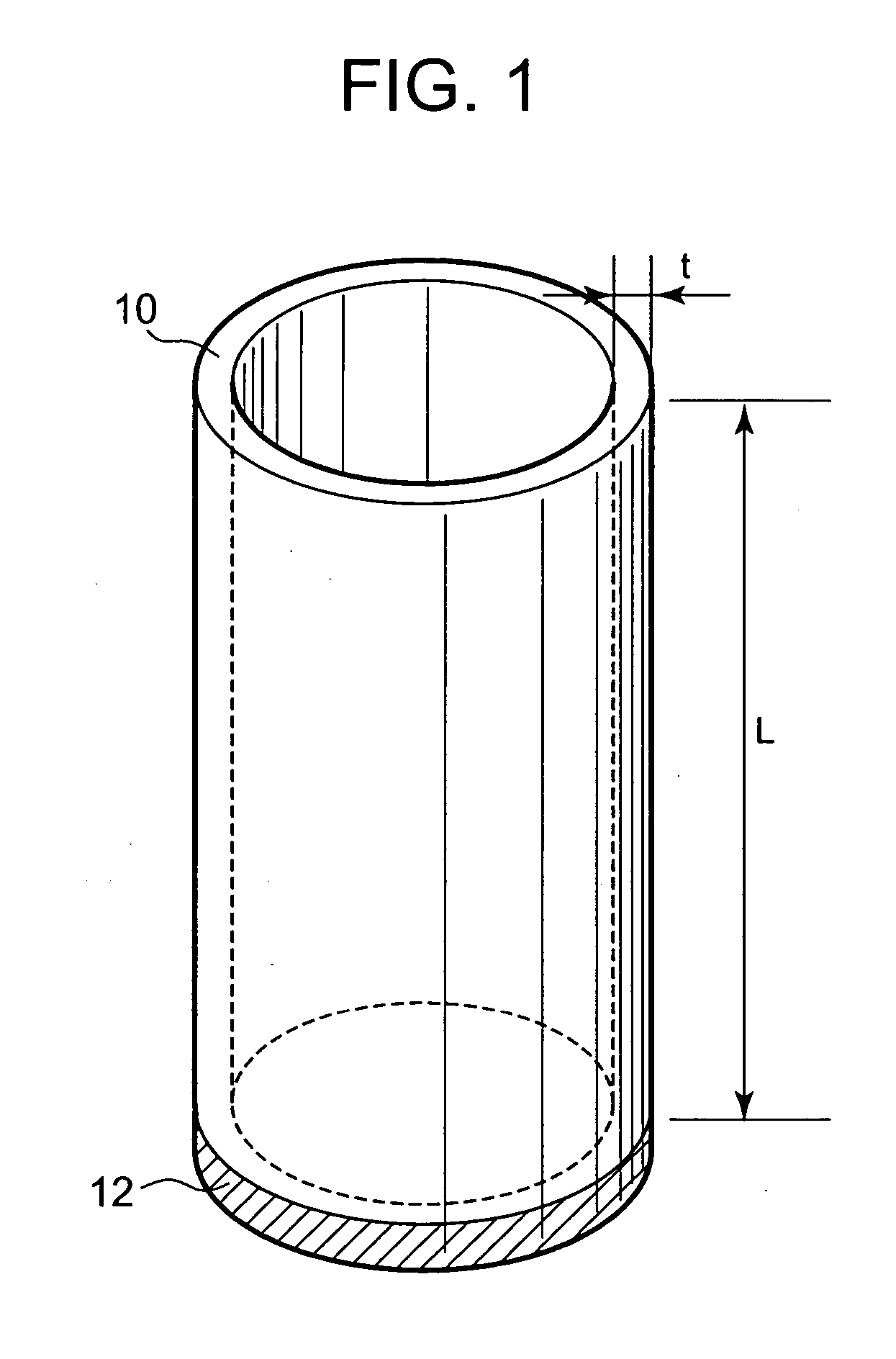
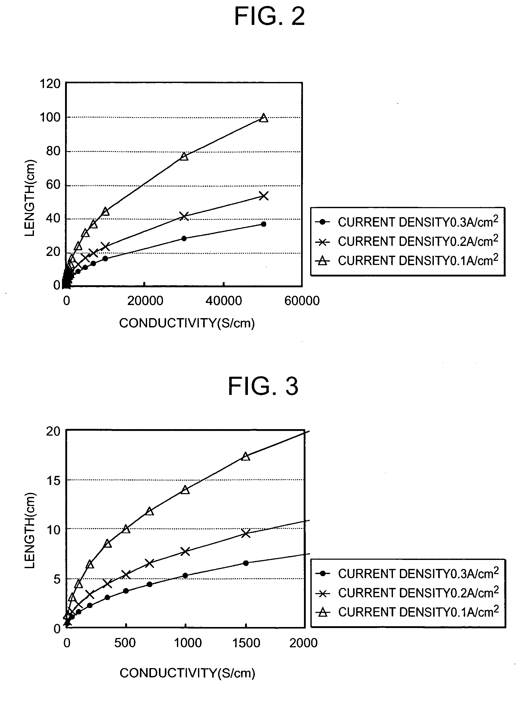
[0049] As shown in FIG. 1, in the case of collecting power from a power collecting section 12 at an end of a cylindrical porous metal substrate 10, a power collection loss occurs due to electric resistance in a longitudinal direction of the cylindrical porous metal substrate 10. Here, a relation between conductivity and a power collection loss of the cylindrical porous metal substrate 10 can be calculated as in the case of a method described in pp. 337 to 340, Electrochemistry 68, No. 5 (2000) by Taniguchi et al., if parameters are set as follows. [0050] L(cm): length of cylindrical porous metal substrate (but ½ of cylindrical porous metal substrate length if power collection is executed from both ends) [0051]σ(S / cm): conductivity of cylindrical porous metal substrate [0052] t(cm): tube thickness of cylindrical porous metal substrate [0053]ρ(Ω / cm2): 1 / (σ(S / cm)×t(cm)×1(cm) [0054] Re(Ωcm2): (electrolytic resistance+anode reaction resistance+cathode reaction resistan...

embodiment 2

[0070] Embodiment 2

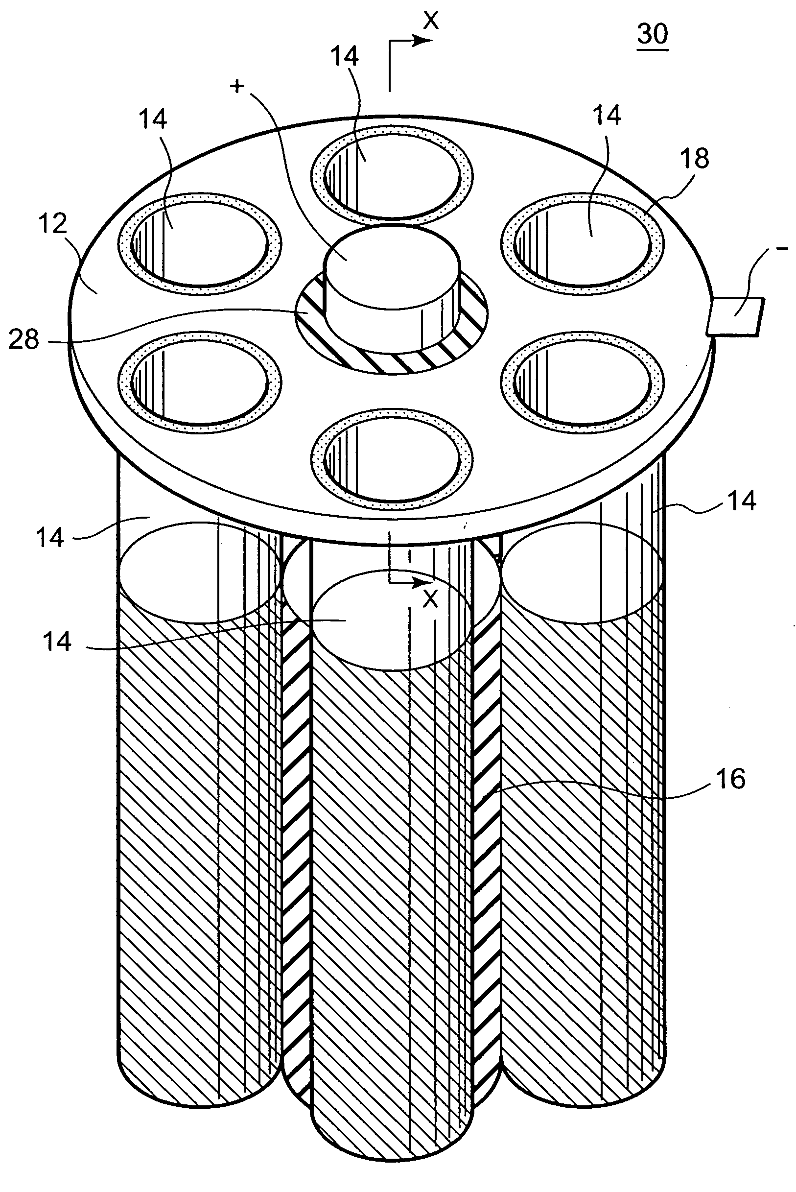
[0071]FIGS. 7 and 8 are perspective and sectional views showing a constitution of an embodiment of the present invention. A reference numeral 12 denotes a first power collection member (metal plate), 14 denotes a single solid oxide fuel cell, and 16 denotes a second power collection member (power collection tube). A cylindrical porous metal substrate 18 of the single cell 14 is manufactured so as to obtain porosity of 40% by a method for mixing→kneading→extrusion→molding→dryingdegreasing→in-vacuum sintering an alloy powder which contains HRE 5 by Hitachi Metals, Ltd. (registered trade mark, Fe—Cr—Al) and whose particle diameter is 10 to 100 μm with a binder. Since conductivity ρ of the cylindrical porous metal substrate 18 is 10000 S / cm, an outer diameter, a tube thickness and a length thereof are respectively 20 mm, 1.5 mm and 30 cm. By using this cylindrical porous metal substrate 18, an oxidant electrode 20, an electrolytic layer 22, and a fuel electrode 24 ar...

embodiment 3

[0090] Embodiment 3

[0091]FIGS. 12 and 13 are perspective and sectional views showing a constitution of another embodiment of the present invention. A cell 14 and two conductive metal plates 12 similar to those of the Embodiment 2 are mechanically and electrically connected together by a rod 32 put through a cylindrical porous metal substrate 18, whereby power collection is carried out on an oxidant electrode 20 side thereon.

[0092] In this case, power collection resistance can be reduced by arranging a conductive sealing material, e.g., a metal ring 34, between the cylindrical porous metal substrate 18 and the two metal plates 12.


PUM


Abstract

A shape and conductivity of a cylindrical porous metal substrate of low power collection losses are defined, and a solid oxide fuel cell of a high output or high start-up performance is provided by using the cylindrical porous metal substrate. In the solid oxide fuel cell of the invention, the cylindrical porous metal substrate which has a conductivity of 130 S / cm or more is used, and a power collecting section is connected to a position which does not exceed 100 cm from any place thereof. A first electrode, a solid electrolytic layer, and a second electrode are formed on a full periphery of the cylindrical porous metal substrate. Thus, it is possible to obtain a solid oxide fuel cell of easy cell formation and low power collection losses, i.e., high durability and a high output.

Description

BACKGROUND OF THE INVENTION [0001] The present invention relates to a solid oxide fuel cell, and more particularly to a shape and a structure of a solid oxide fuel cell which comprises a cylindrical porous metal substrate and takes power collection losses into consideration. [0002] As a conventional cylindrical solid oxide fuel cell (SOFC) 50, as shown in FIG. 16, a type is generally used in which a solid oxide electrolyte layer 54 and a fuel electrode 56 are sequentially formed into circular arc shapes on a cathode tube 52 constituted of a porous cylinder that also serves as an oxidant electrode, and an interconnector layer 58 is formed in cut-off parts of the circular arcs to be brought into contact with an outer surface of the cathode tube 52 and extended in a longitudinal direction thereof. It is because if the cathode tube 52 is formed by using a material whose conductivity is not high, power must be collected on the oxidant electrode side by forming the interconnector layer 58...

Claims


Application Information

Patent Timeline
IPC IPC(8): H01M2/02H01M4/86H01M8/00H01M8/02H01M8/04H01M8/06H01M8/10H01M8/12H01M8/24
CPCH01M8/0206H01M8/0228H01M8/0247H01M8/025Y02E60/525H01M8/1226H01M8/243H01M2008/1293Y02E60/50H01M8/0258H01M8/02H01M8/24H01M8/0267
Inventor OKAMOTO, TAKASHITANIGUCHI, SHUNSUKE
Owner SANYO ELECTRIC CO LTD
Learn More