
Folded metal bipolar sheets for fuel cells

a technology of bipolar sheets and fuel cells, applied in the field of bipolar separator plates, can solve the problems of difficult engineering problems, close tolerances, and control of fuel cells, and achieve the effects of improving the efficiency of fuel cells

Active Publication Date: 2004-11-11
GAS TECH INST
View PDF2 Cites 11 Cited by
  • Summary
  • Abstract
  • Description
  • Claims
  • Application Information

AI Technical Summary

Benefits of technology

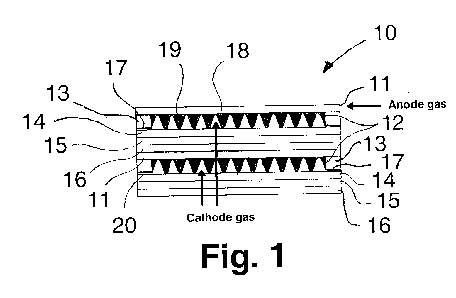
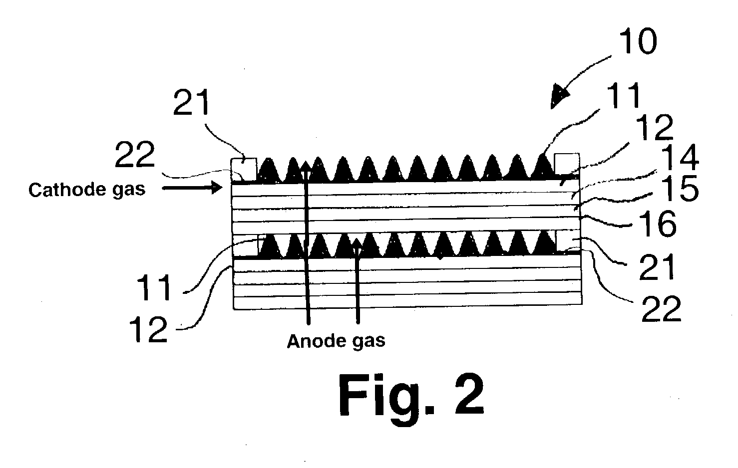
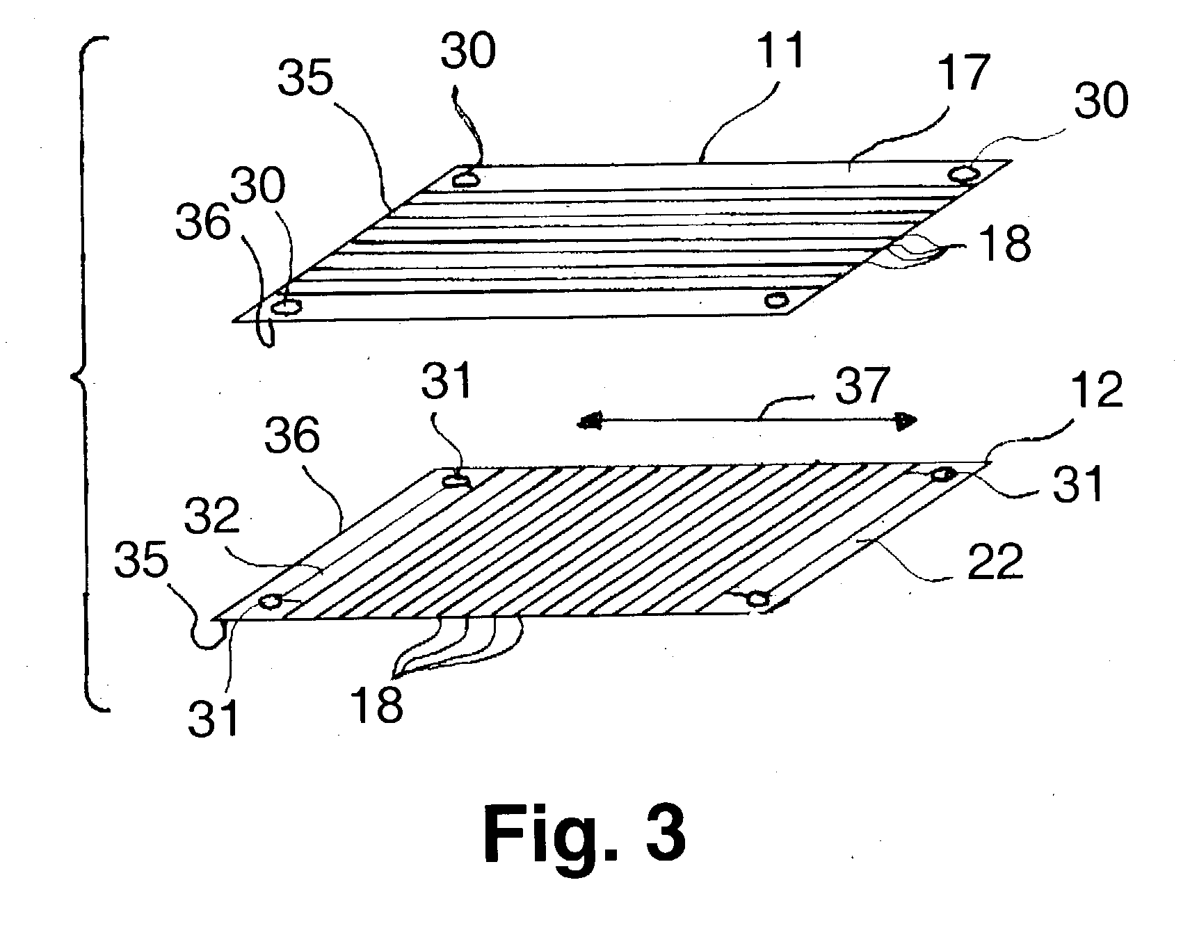
[0015] These and other objects of this invention are addressed by a separator plate comprising two joined together coextensive separator plate elements having perpendicularly disposed corrugated regions and forming a coolant chamber there between, each of the separator plate elements having an electrode facing face and a coolant facing face. Two flattened peripheral seal regions extend along opposed edges of each of the separator plate elements, which opposed edges extend perpendicular to the direction of corrugation of the corrugated region of the particular separator plate element. A first gasket material is disposed in the flattened peripheral seal regions on the coolant facing face of one of the separator plate elements and in the flattened peripheral seal regions on the electrode facing face of the other separator plate element. A second gasket material is disposed in the flattened peripheral seal regions on the opposite faces of the separator plate elements in which the first gasket material is disposed. A filler material is disposed within the corrugations on the coolant facing faces along non-flattened edges of the separator plate elements, whereby a peripheral seal is effected between the separator plate elements by the combination of gasket materials and filler material. Coolant means are provided for introducing a coolant into the coolant chamber. In accordance with a particularly preferred embodiment of this invention, the separator plate elements are constructed of folded metal sheets. Folding of metal sheets to produce the separator plate elements does not stretch the metal, thereby obviating the need for the 50%-elongation required for press forming. Thus, virtually any metal, including corrosion resistant metals, as well as refractories having poor press-forming properties, such as elongation, etc., can be formed by folding to produce the corrugated separator plate elements of the bipolar separator plates of this invention. Yet a further benefit of using a folding method for producing the separator plate elements is that essentially any combination of peak-to-peak distances and depths of valleys or channels is possible.

Problems solved by technology

One issue associated with successful operation of each of these fuel cell types is the control of fuel cell temperature and the removal of products generated by the electrochemical reactions from within the fuel cell.
Fuel cell stacks containing a plurality of fuel cell units may be up to several feet tall, presenting serious problems with respect to maintaining cell integrity during heat-up and operation of the fuel cell stack.
Due to thermal gradients between the cell assembly and cell operating conditions, differential thermal expansions, and the necessary strength of materials required for the various components, close tolerances and very difficult engineering problems are presented.
In this regard, cell temperature control is highly significant and, if it is not accomplished with a minimum temperature gradient, uniform current density will not be maintainable, and degradation of the cell will occur.
However, press forming of sheet metal requires costly die molds and requires that the metal have an elongation of greater than about 50%, which severely limits the metals available for use in the corrosive environments of polymer electrolyte membrane fuel cells or the high temperature environments of molten carbonate fuel cells and solid oxide fuel cells.
In addition, press forming of thin sheets of metal to produce bipolar separator plates disadvantageously results in plates having stresses which must be relieved, typically by high temperature annealing, prior to use.
Furthermore, depending upon the plate design, press forming results in a plate in which some portions of the formed metal are thinner than other portions due to metal thinning.
As a result, for a given metal sheet thickness, the heights of the peaks as well as the distances between the peaks, hereinafter sometimes referred to as "pitch," are significantly limited.

Method used


Image

  • Folded metal bipolar sheets for fuel cells
  • Folded metal bipolar sheets for fuel cells
  • Folded metal bipolar sheets for fuel cells

Examples


example

[0030] The manufacture, assembly and operation of a bipolar separator plate in accordance with one exemplary embodiment of this invention starts with a thin, flat sheet of metal, having a thickness in the range of about 0.001 to about 0.020 inches, preferably in the range of about 0.001 to about 0.010 inches, which is fed into a set of rotating "gears" so as to fold the metal into the desired shape. Devices for this purpose are well known to those skilled in the art and, thus, will not be discussed in detail herein. The "pitch" is defined as the distance between peaks on one side of the folded separator plate element and "depth" is defined as the distance from the "valley" or "channel" disposed between two peaks to the top of the peaks. For purposes of this exemplary embodiment, a depth of about 0.037 inches, a pitch of about 0.055 inches and a metal thickness of about 0.003 inches are selected. When a flat continuous sheet 12 inches in width is fed into the folding device, a contin...


PUM


Abstract

In a fuel cell stack, a bipolar separator plate having two joined together coextensive separator plate elements having perpendicularly disposed corrugated regions and forming a coolant chamber there between. By virtue of this arrangement, fuel and oxidant gases fed to the fuel cell stack have a cross-flow relationship. Internal stack manifolding is provided for distribution of a coolant to each of the coolant chambers.

Description

[0001] 1. Field of the Invention[0002] This invention relates generally to bipolar separator plates for use in connection with substantially planar electrochemical fuel cell units for generating electricity, and fuel cell stacks comprising such fuel cell units. More particularly, this invention relates to gas (e.g. air) and / or liquid cooled, bipolar sheet metal separator plates for use in polymer electrolyte membrane fuel cells. Although the concept of this invention may be applied to bipolar separator plates for a variety of fuel cell types and designs, including molten carbonate and solid oxide fuel cells, it is particularly suitable for use in polymer electrolyte membrane fuel cell stacks in which the fuel and oxidant are provided to each of the fuel cell units comprising the fuel cell stack through external manifolds.[0003] 2. Description of Related Art[0004] Fuel cells are electrochemical devices that convert chemical energy of a reaction directly into electrical energy. The ba...

Claims


Application Information

Patent Timeline
IPC IPC(8): H01M8/02H01M8/04
CPCH01M8/0206H01M8/0228H01M8/0254H01M8/0267H01M8/0271H01M8/04007Y02E60/50H01M8/2483H01M8/244H01M8/2432H01M8/2457H01M8/026H01M8/241
Inventor MARIANOWSKI, LEONARD G.KONCAR, GERALD J.FAN, QINBAICHERVINKO, JEREMY
Owner GAS TECH INST
Learn More