
Serial flash integrated circuit having error detection and correction

a technology of integrated circuits and serial flash, which is applied in error detection/correction, redundancy data error correction, instruments, etc., can solve problems such as flash memory arrays to loose their value, data errors occasionally occurring in flash memory, and flash memory arrays to lose valu

Inactive Publication Date: 2004-08-05
WINBOND ELECTRONICS CORP
View PDF20 Cites 329 Cited by
  • Summary
  • Abstract
  • Description
  • Claims
  • Application Information

AI Technical Summary

Problems solved by technology

Unfortunately, data errors occasionally occur in flash memory.
These data errors sometimes occur due to defects arising in the manufacturing process, but they can also occur as the memory is used because of two phenomena inherent to the flash data cell: memory disturb and oxide rupture.
Memory disturb and oxide rupture will both cause a data cell in a flash memory array to loose its value.
Memory disturb is a much more serious problem in flash memories used with applications that generally perform random writes than in flash memories used with applications that generally perform sequential writes.
Writing data in random order on the flash media causes more stress to the data cells than writing data in sequential order, so that the accumulated stress is greater and memory disturb more frequent in flash memories used with random writing applications.
However, data refresh is very demanding on the firmware and system using the flash device, and often cannot be accommodated for in system designs.
Examples of the demands made by data refresh include power consumption, use of clock cycles to the detriment of other memory processes, and tying up of system resources.
This means that under most circumstances, the part will be prematurely worn by refreshing too often, leading to such failure modes as oxide rupture.
However, Hamming codes are limited in that they are only able to correct a single bit.
While such chips can be easily implemented by a designer into an application, the amount of combinational logic required makes the use of parallel encode and decode only practical with small ECC codewords.
Unfortunately, ECC systems with small codewords have a significant disadvantage.
These high overheads increase the chip size and therefore significantly increase the cost of adding ECC function to semiconductor memory.
The increased amount of combinational logic requires more chip area and increases fabrication cost.
The second major drawback of the parallel processing ECC system disclosed by Tanzawa et al. is the reliance on a code that only can only guarantee correcting a single bit.
The use of larger ECC codewords increases the chance of multiple errors occurring within a codeword.
If multiple errors occur in an ECC system with only single bit correction capability, the data is not recoverable.
Unfortunately, if there are even just two errors, the chance that the second error falls within the same codeword as the first error is 1 in 8, or 12.5%.
This means that 12.5% of all two bit errors are not correctable by this ECC system.
This system therefore always reads two times, even if there is no error, and therefore adds an "unnecessary" delay to the delivery of valid data.
While large codewords are advantageous in semiconductor memories with on-chip ECC systems because of their low overhead, conventional large codeword systems such as disclosed in the Tanzawa et al. and Nozoe et al. patents are not extendable to multiple bit correction.
Read syndromes are not directly generated in large ECC codeword semiconductor memory systems because the amount of combinational logic that would be required would be impractically large.
This limits this type of ECC systems to the correction of single errors.
Because of the complexity and cost of the multiple chip ECC system, the memory array protected by the ECC system is typically large, and is typically composed of an arrangement of multiple high density flash devices.

Method used


Image

  • Serial flash integrated circuit having error detection and correction
  • Serial flash integrated circuit having error detection and correction
  • Serial flash integrated circuit having error detection and correction

Examples


Embodiment Construction

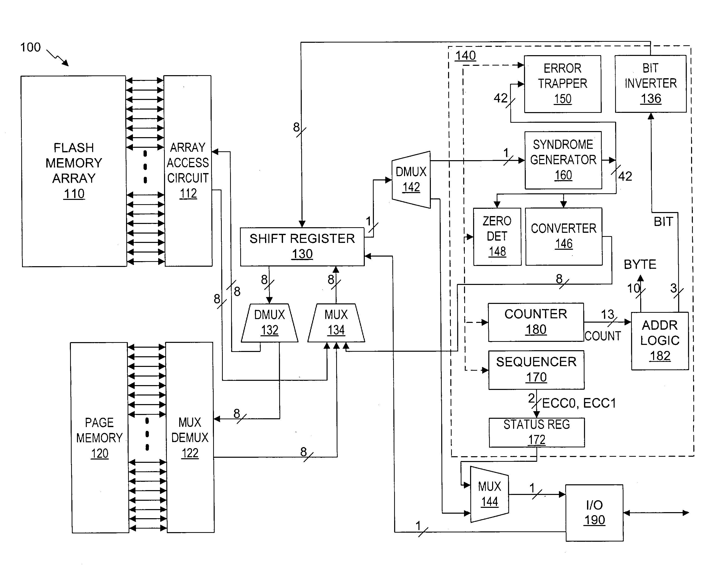
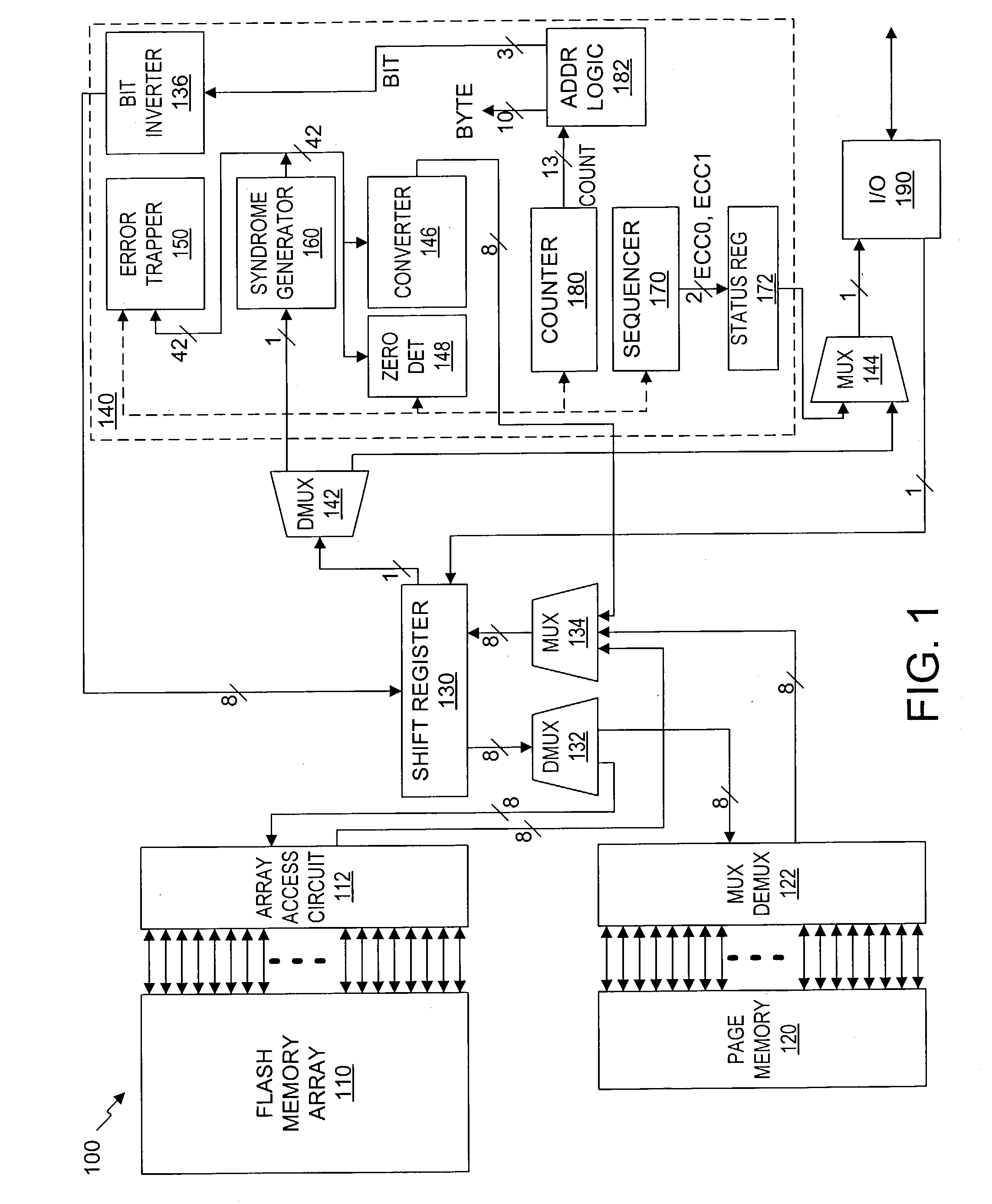
[0062] As shown in the illustrative embodiment of FIG. 1, a serial flash memory 100 is provided with an integrated error correction coding ("ECC") system 140 that is used with an integrated volatile page memory 120 for fast automatic data correction (AutoCorrect). Preferably, the ECC code has the capability of correcting any one or two bit error that occurs in a page between writing and reading. One bit corrections are done automatically in hardware during reads or transfer to the page memory 120 (AutoCorrect), while two-bit corrections are handled in external software, firmware or hardware. The use of ECC is optional, so that command sets may include ECC read and ECC write commands as well as non-ECC read and non-ECC write commands. The serial flash memory 100 also includes any suitable internal data path that is controllably configurable for the various operational modes of the serial flash memory 100. An illustrative data path in FIG. 1 includes the various multiplexers 132, 134,...


PUM


Abstract

A serial flash integrated circuit is provided with an integrated error correction coding ("ECC") system that is used with an integrated volatile page memory for fast automatic data correction. The ECC code has the capability of correcting any one or two bit errors that might occur on a page of the flash memory array. One bit corrections are done automatically in hardware during reads or transfer to the page memory, while two-bit corrections are handled in external software, firmware or hardware. The ECC system uses a syndrome generator for generating both write and read syndromes, and an error trapper to identify the location of single bit errors using very little additional chip space. The flash memory array may be refreshed from the page memory to correct any detected errors. Data status is made available to the application prior to the data. The use of the ECC is optional.

Description

[0001] 1. Field of the Invention[0002] The present invention relates to nonvolatile semiconductor memory integrated circuits, and more particularly to a serial flash memory integrated circuits having error detection and correction.[0003] 2. Description of the Related Art[0004] A "flash" memory array is a type of nonvolatile semiconductor memory array that retains stored data when power is removed. Many different types of data cells suitable for flash memory are known, including a class of single transistor devices that are based on the storage of charge in discrete trapping centers of a dielectric layer of the structure, and another class of devices that are based on the storage of charge on a conducting or semiconducting layer that is completely surrounded by a dielectric, typically an oxide. Stored charge typically is in the form of electrons, which typically are removed from the charge storage structure using the Fowler-Nordheim mechanism to achieve one state, typically called an...

Claims


Application Information

Patent Timeline
IPC IPC(8): G06F11/10G11C29/00
CPCG11C2216/30G06F11/1068
Inventor MACHADO, MICHAEL G.VAN GENDEREN, CHRISLEE, POONGYEUBPARK, JOO WEON
Owner WINBOND ELECTRONICS CORP
Learn More