
Reflective Arrayed Waveguide Grating

a waveguide and array technology, applied in the field of photonic integrated circuits, can solve the problems of higher insertion loss, packaging loss, long waveguide length in the array, etc., and achieve the effect of shortening waveguide length, and reducing chip size and on-chip losses

Inactive Publication Date: 2004-06-03
APPLIES RES & PHOTONICS
View PDF17 Cites 13 Cited by
  • Summary
  • Abstract
  • Description
  • Claims
  • Application Information

AI Technical Summary

Benefits of technology

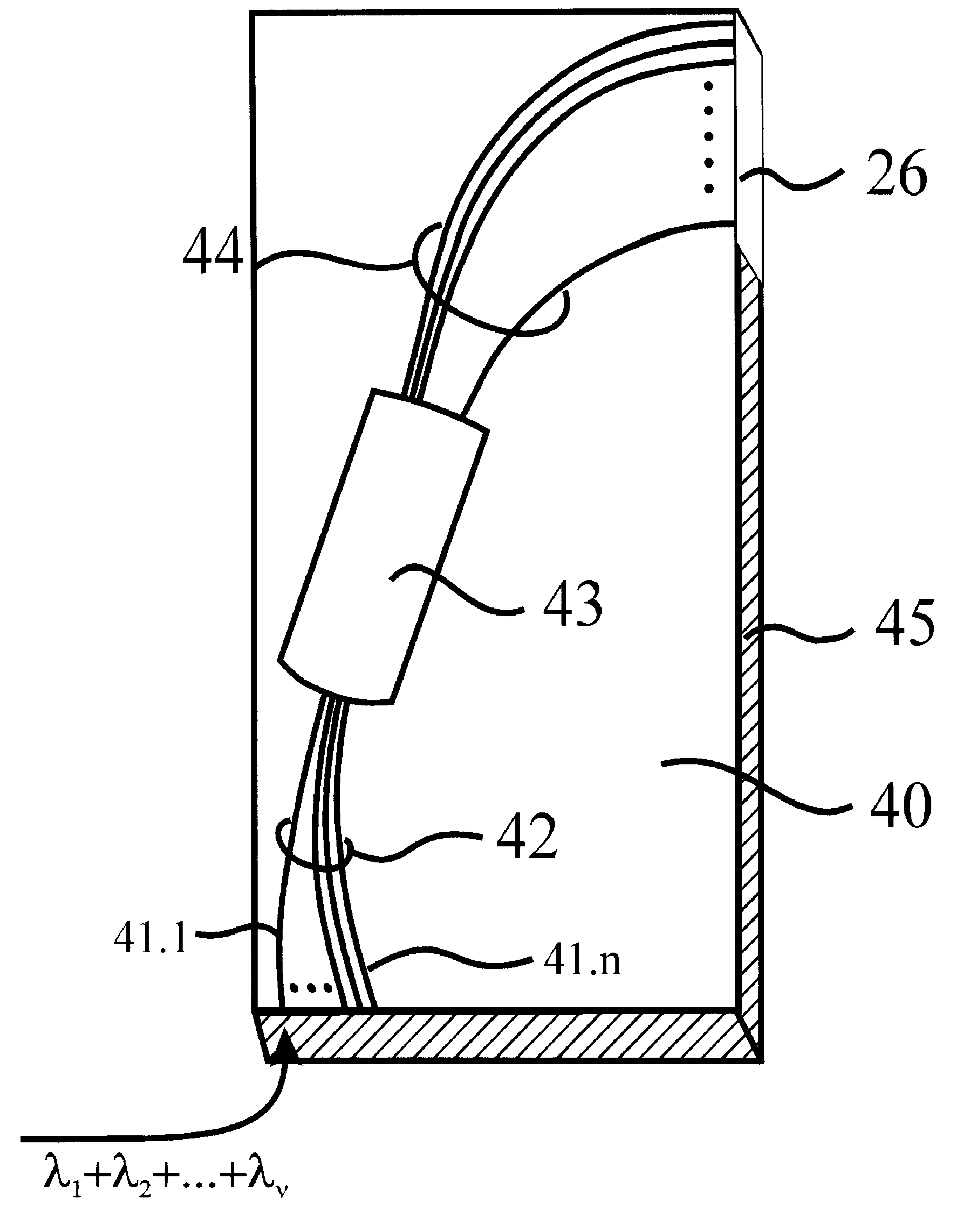
[0017] This invention discloses a "reflective arrayed waveguide grating," (RAWG) for optical multiplexing and demultiplexing applications that uses a single slab for both input and output. It also uses shorter length of the waveguides in the array, thereby reducing the chip size to half compared to a TAWG. By eliminating one of the slabs, the design allows for a single external fiber array interface to the chip. These factors reduce the chip size and on-chip losses significantly. Moreover, the waveguide lengths are also half compared to what is necessary for a TAWG, thus contributing to lower insertion loss and significant savings of the silicon real estate. The smaller chip size increases the reliability of the device significantly and almost doubles the yield of chips per wafer. Used as a "building block," these chips enable fabrication of several passive and active modules in an integrated platform.

Problems solved by technology

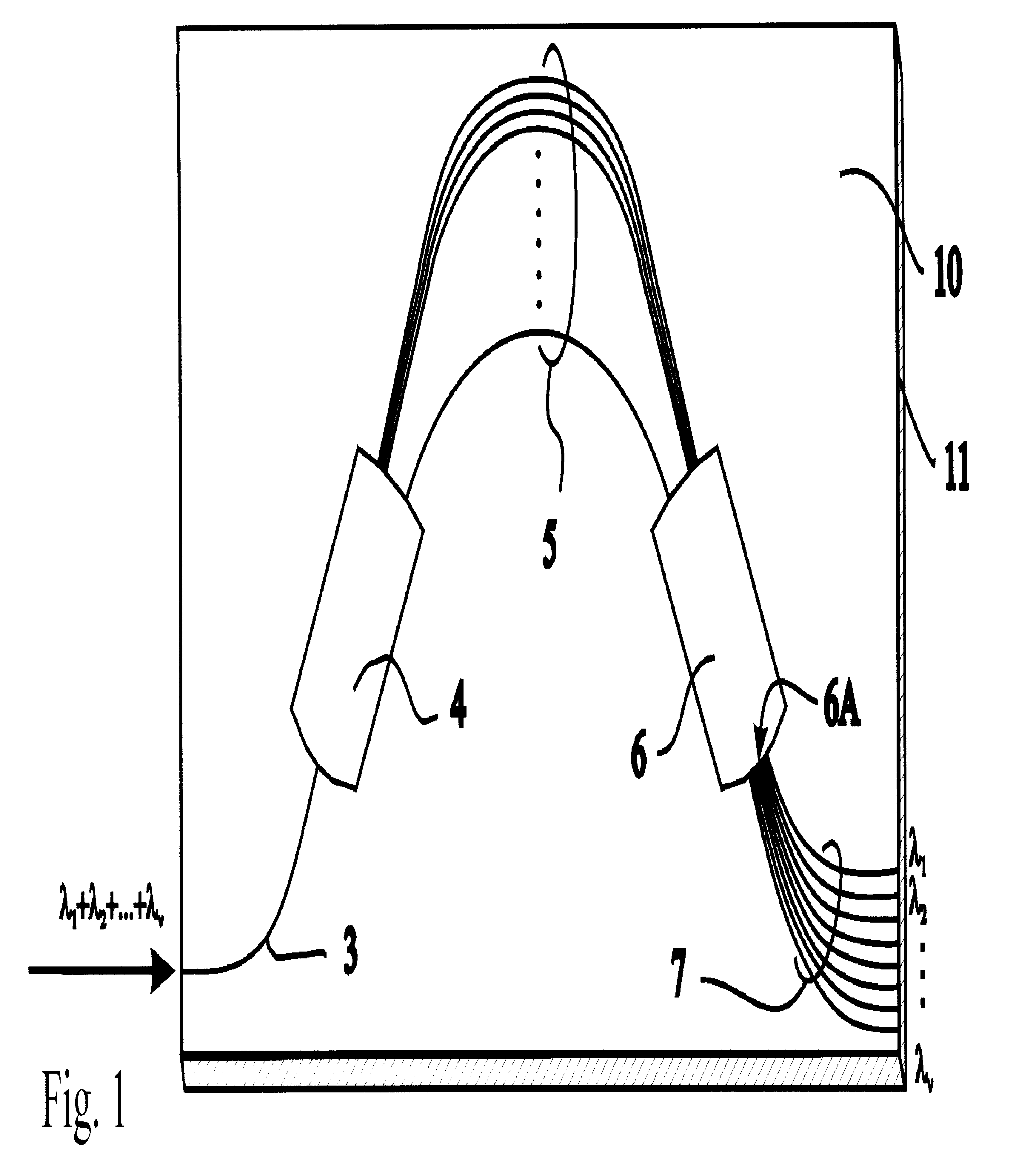
The TAWG described above suffers from several disadvantages such as bigger area per device, longer waveguide lengths in the array, and two different slabs for input and output, all of which contribute to a higher insertion loss.
Having two different external interfaces is also disadvantageous, because, attaching two different fiber arrays increases the packaging loss, makes it relatively less reliable, and increases chance of failure.
In all cases, however, size reduction is accompanied by a higher loss and lower performance.

Method used


Image

  • Reflective Arrayed Waveguide Grating
  • Reflective Arrayed Waveguide Grating
  • Reflective Arrayed Waveguide Grating

Examples


Embodiment Construction

[0032] The current invention describes a solution to the size reduction problem with a goal to reduce the chip size with simultaneous improvement of performance in terms of reduced loss and external interface. The most compelling rationale for size reduction are: (i) yield per wafer will increase as the size per chip is reduced; this in turn will cut the cost of the devices, (ii) smaller chip size will result in smaller package size, and (iii) it is easier to maintain temperature uniformity of a smaller chip and smaller package which is crucial for reliable device operation.

[0033] In addition to the size reduction, other objectives of the present invention are to reduce the on-chip loss and also to reduce the external interfaces to improve the reliability of the devices built around this chip. The device disclosed herein accomplishes all three objectives. A further objective is to use these chips as a building block for triple-phase integration.

DETAILED DESCRIPTION OF PREFERRED EMBO...


PUM


Abstract

This invention discloses a "reflective arrayed waveguide grating," (RAWG) for demultiplexing a multiplexed optical signal into its component wavelengths and for multiplexing n optical signals into a multiplexed signal. The present invention found that a single slab can be used for coupling the signal in and for focusing the signal out of the array of waveguide that functions as a grating; and a single external fiber array interface containing plurality of fibers can be used for both inputting the signal in and for outputting the signal from the RAWG. Advantageously, this method reduces the chip size and on-chip insertion loss by eliminating a slab and using 50% shorter waveguides in the array allowing significant savings of the silicon real estate. The smaller chip size increases the reliability of the device significantly and almost doubles the yield of chips per wafer. Additionally, used as a building block, these chips can enable further functionality enhancement via tiers of monolithic triple-phase integration.

Description

BACKGROUND OF INVENTION[0001] 1. Field of Invention[0002] This invention relates to a photonic integrated circuit, specifically to a reflective arrayed waveguide grating, that is used for wavelength division multiplexing and demultiplexing for fiberoptic communication networks. It also relates to several other passive and active photonic device applications in the capacity of a building block via triple-phase integration described herein.[0003] 2. Description of the Prior Art[0004] Recently arrayed waveguide gratings (AWGs) have proven to be an attractive vehicle for achieving high channel count wavelength division multiplexing (WDM) (see for example "An N.times.N optical multiplexer using a planar arrangement of two star couplers" disclosed by C. Dragone in IEEE Photonic Technology Letters, vol. 3, no. 9, 1991, pp 812815, or U.S. Pat. No. 0,033,715 A1 titled "Arrayed waveguide grating having a reflective input coupling," Delisle, et al., Oct. 25, 2001). The basic strength and cost ...

Claims


Application Information

Patent Timeline
IPC IPC(8): G02B6/12G02B6/34
CPCG02B6/12007G02B6/12019G02B6/12011
Inventor RAHMAN, ANIS
Owner APPLIES RES & PHOTONICS
Learn More