
Flexible imaging member seam treatment apparatus

a technology of flexible imaging and treatment apparatus, which is applied in the direction of electric/magnetic/electromagnetic heating, instruments, applications, etc., to achieve the effect of improving surface morphological profile, good seam region physical continuity, and effective invention of seam area overcoating/lamination

Inactive Publication Date: 2004-03-25
XEROX CORP
View PDF8 Cites 7 Cited by
  • Summary
  • Abstract
  • Description
  • Claims
  • Application Information

AI Technical Summary

Benefits of technology

[0011] Under dynamic fatiguing conditions, the seam provides a focal point for stress concentration and becomes the point of crack initiation which is further developed into seam delamination causing premature mechanical failure in the belt. Thus, the splashing tends to shorten the mechanical life of the seam and service life of the flexible member belts used in copiers, duplicators, and printers.
[0078] Thus, the process and apparatus of embodiments as shown in the examples described above produce a flexible imaging member in which the seam has a protective overcoating substantially free of protrusions, a smooth surface profile, and that exhibits good physical continuity. Additionally, the seam area produced by embodiments has reduced seam area thickness and enjoys reduced fatigue induced bending seam stress cracking under dynamic belt flexing conditions over the rollers of a belt support module during imaging machine operation. Furthermore, treating according to embodiments can substantially enhance imaging member production yield, effectively reducing the belt unit manufacturing cost. Because successful implementation of embodiments greatly reduces of substantially eliminates the need of labor-intensive and time-consuming manual seam inspection procedures, embodiments also effectively increase production belt yield by recovery of those belts that are otherwise lost as rejects due to the presence of seam protrusions. Thus, embodiments deliver a seam configuration with significantly improved qualities, better physical / mechanical attributes, such as smoother surface profile, absence of protrusion spots, thinner cross-section thickness, and little or no physical discontinuity to enhance cleaning blade performance and suppress the premature onset of fatigue induced seam cracking / delamination problem during extended electrophotographic imaging and cleaning processes.

Problems solved by technology

Although excellent toner images can be obtained with multilayered belt photoreceptors, it has been found that as more advanced, higher speed electrophotographic copiers, duplicators and printers are developed, fatigue-induced cracking of the charge transport layer at the welded seam area is frequently encountered during photoreceptor belt cycling.
Moreover, the onset of seam cracking has also been found to rapidly lead to seam delamination due to fatigue, shortening belt service life.
Dynamic fatigue seam cracking can possibly happen in ionographic imaging member belts as well.
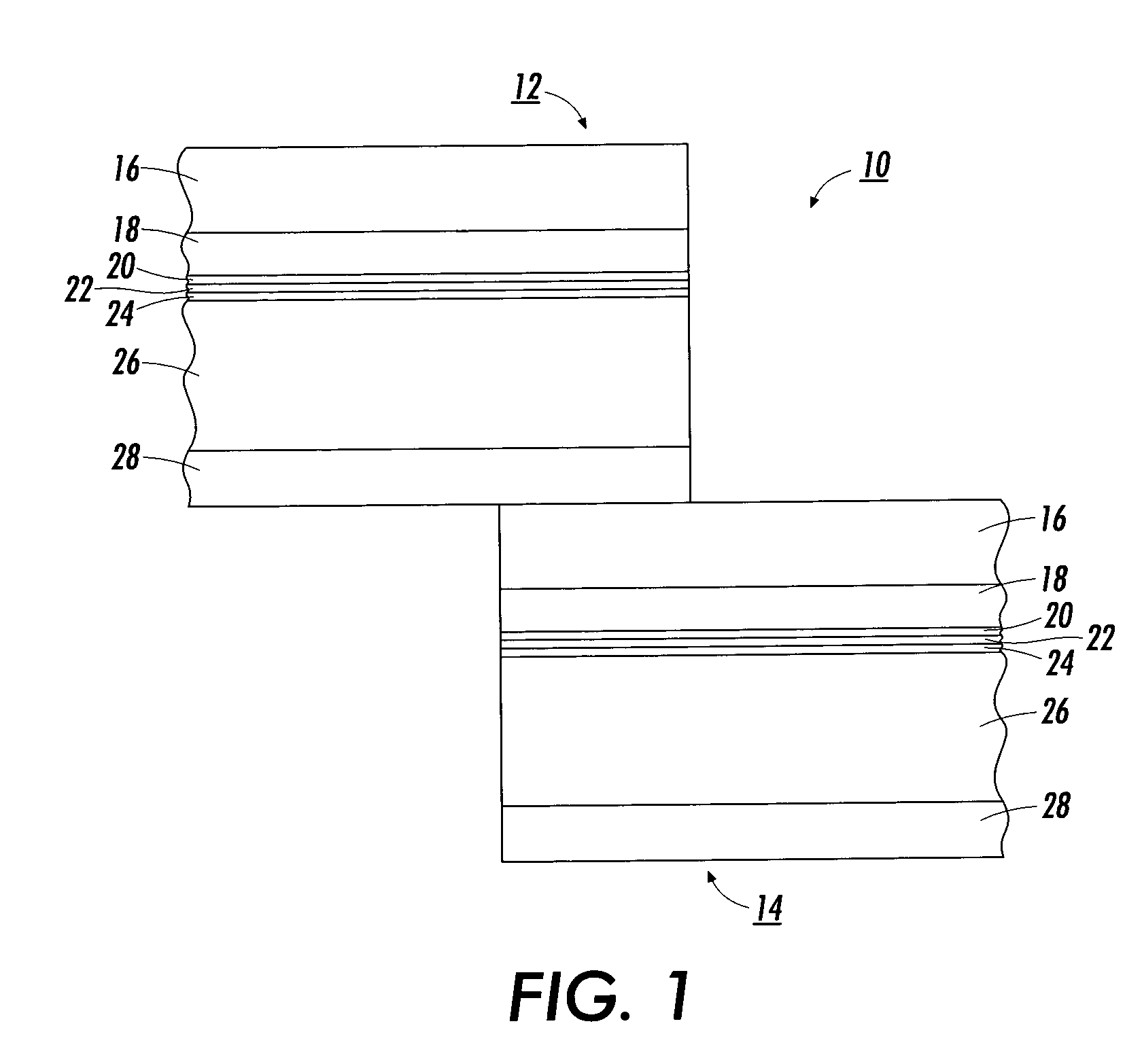
When ultrasonically welded into a belt, the seam of multilayered electrophotographic imaging flexible members can occasionally contain undesirable high protrusions such as peaks, ridges, spikes, and mounds.
These seam protrusions present problems during image cycling of the belt machine because they interact with cleaning blades to cause blade wear and tear, which ultimately affects cleaning blade efficiency and service life.
Moreover, the protrusion high spots in the seam can also interfere with the operation of subsystems of copiers, printers and duplicators by damaging electrode wires used in development subsystems that position the wires parallel to and closely spaced from the outer imaging surface of belt photoreceptors.
Another frequently observed mechanical failure in the imaging belts during image cycling is that, after being subjected to extended bending and flexing cycles over small diameter belt support rollers, the ultrasonically welded seam of an electrophotographic imaging member can develop cracks that propagate and lead to delamination of the belt.
Additionally, such cracking and delamination can result from lateral forces caused by mechanical rubbing contact against stationary web edge guides of a belt support module during cycling.
Alteration of materials in the various photoreceptor belt layers such as the conductive layer, hole blocking layer, adhesive layer, charge generating layer, and / or charge transport layer to suppress cracking and delamination problems is not easily accomplished.
The alteration of the materials can adversely impact the overall physical, electrical, mechanical, and other properties of the belt such as well as coating layer uniformity, residual voltage, background, dark decay, flexibility, and the like.
The ultrasonic welded seam of a multilayered photoreceptor belt is relatively brittle and low in strength and toughness.
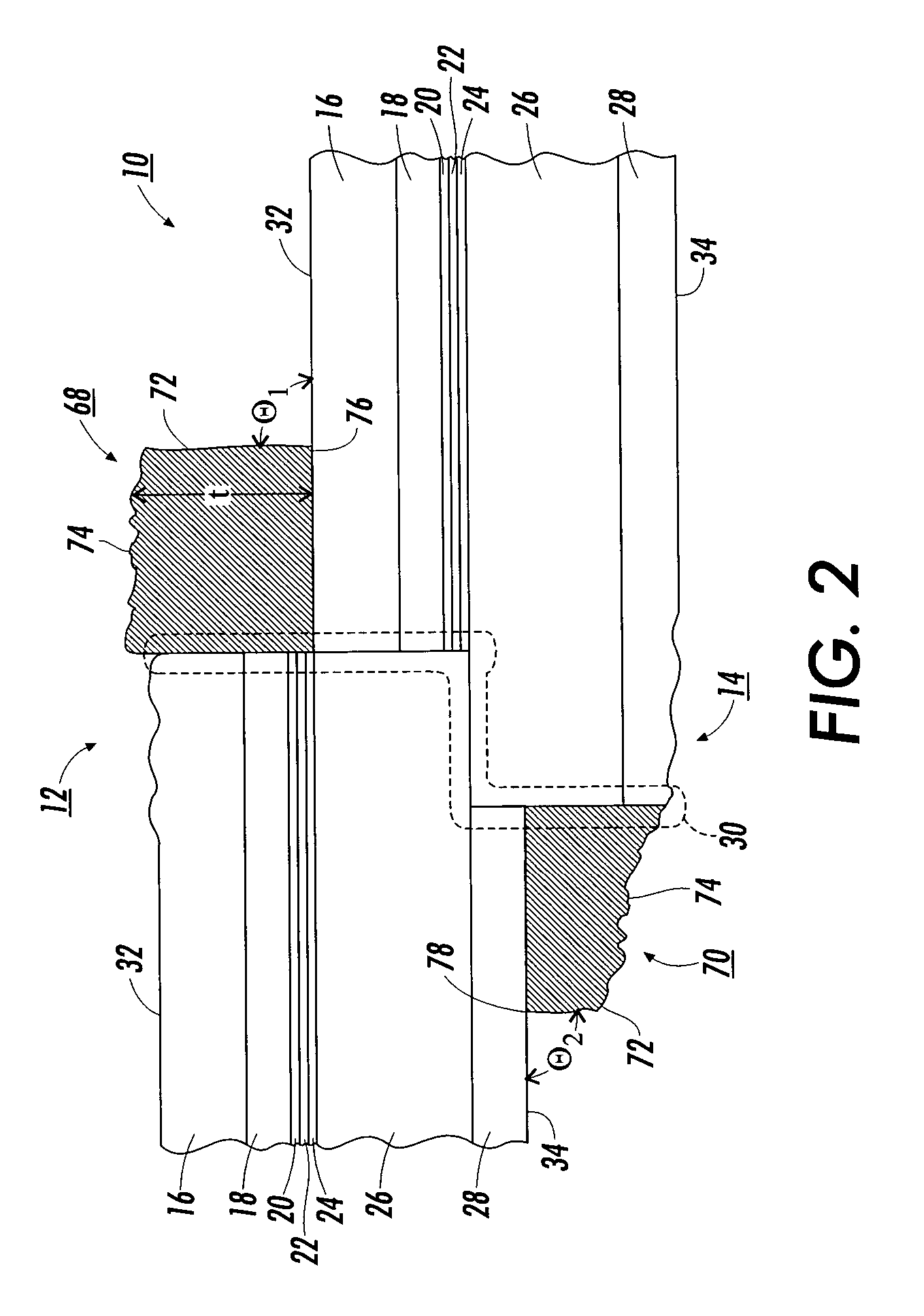
The joining techniques, particularly the welding process, can result in the formation of a splashing that projects out from either side of the seam in the overlap region of the belt.
The excessive thickness of the photoreceptor belt in the seam region due to the presence of the splashing results in a large induced bending strain as the seam travels over each roller.
Unfortunately, small diameter rollers, e.g., less than about 0.75 inch (19 millimeters) in diameter, raise the threshold of mechanical performance criteria to such a high level that photoreceptor belt seam failure can become unacceptable for multilayered belt photoreceptors.
Under dynamic fatiguing conditions, the seam provides a focal point for stress concentration and becomes the point of crack initiation which is further developed into seam delamination causing premature mechanical failure in the belt.
Thus, the splashing tends to shorten the mechanical life of the seam and service life of the flexible member belts used in copiers, duplicators, and printers.
Although a solution to suppress the seam cracking / delamination problems has been successfully demonstrated, as described in a prior art, by a specific heat treatment process of a flexible electrophotographic imaging member belt with its seam parked directly on top of a 19 mm diameter back support rod for stress-releasing treatment at a temperature slightly above the glass transition temperature (Tg) of the charge transport layer of the imaging member, nevertheless this seam stress release process was also found to produce various undesirable effects such as causing seam area imaging member set and development of belt ripples in the active electrophotographic imaging zones of the belt (e.g., the region beyond about 25.2 millimeters from either side from the midpoint of the seam).
Moreover, the heat treatment can induce undesirable circumferential shrinkage of the imaging belt.
The set in the seam area of an imaging member mechanically adversely interacts with the cleaning blade and impacts cleaning efficiency.
The ripples in the imaging member belt manifest themselves as copy printout defects.
Further, the heat induced imaging belt dimensional shrinkage alters the precise dimensional specifications required for the belt.
Since the belt must be cooled to below the glass transition temperature of the thermoplastic material in the belt prior to removal from the support rod to produce the desired degree of seam stress release in each belt, the heat treatment and cooling cycle time is unduly long and leads to very high belt production costs.
Additionally, such seam heat treatment stress-release processing does not produce the desired seam surface smoothing and protrusion spot elimination.
Both the time consuming procedure of manual inspection and the number of seamed belts rejected due to the presence of high seam protrusions constitute a substantial financial burden on the production cost of imaging members.
While these and other innovative prior art approaches provided improved flexible belt seam morphology, nevertheless it has been found that solution of one problem has also created new undesirable issues.
For example, overcoating the seam of a photoreceptor belt with metallic foil can cause electrical seam arcing as the belt cycles beneath a charging device during electrophotographic imaging processes.
Additionally, application of liquid overcoating layer over the seam induced charge transport molecule crystallization in the vicinity of the seam overcoat, not to mention that liquid overcoating layer can produce poor adhesion bond strength to the seam after solidification into a dried coat.
The amount of the debris, however, is beyond the removal capacity of the cleaning instrument, and portions of the highly concentrated debris are deposited onto the surface of the flexible electrophotographic imaging member 10.
The upward movement of the flap presents an additional problem during the cleaning operation.
As the cleaning instrument strikes the flap, great force is exerted on the cleaning instrument which can lead to damage thereof, e.g., excessive wear and tearing of the cleaning blade.
In addition to damaging the cleaning blade, the striking of the flap by the cleaning instrument causes unwanted vibration in the flexible electrophotographic imaging member 10.
This unwanted vibration adversely affects the copy / print quality produced by the flexible electrophotographic imaging member 10.
However, the radius at the waist of the wheel should not be so small that rigidity of the compression wheel is compromised.

Method used


Image

  • Flexible imaging member seam treatment apparatus
  • Flexible imaging member seam treatment apparatus
  • Flexible imaging member seam treatment apparatus

Examples


example ii

Treatment Article Preparation and Application

[0083] No Substrate

[0084] Six thermoplastic polymer coating solutions were prepared by dissolving Makrolon 5705 polycarbonate with varying amount of charge transport compound N,N'-diphenyll-N,N'-bis(3-methylphenyl)-1,1'-bisphenyl--4,4'-diamine in methylene chloride. The prepared solutions were each applied over a releasing substrate and dried at 257.degree. F. (125.degree. C.) in an air circulating oven for 5 minutes to rid the solvent and then removed from the release substrates to give thermoplastic polymer layers containing 0% wt, 10% wt, 20% wt, 30% wt, 40% wt, and 50% wt charge transport compound in each respective 25 micrometer thick layer. The thermoplastic polymer layers were each analyzed for glass transition temperature, T.sub.g, using differential scanning calorimetric method. The results obtained, listed in the table below, showed that the addition of charge transport compound to the Makrolon could provide successive suppressi...

example iii

Treatment Article Preparation and Application

[0087] Substrate

[0088] A coating solution, prepared by dissolving 10 grams of Makrolon in 90 grams of solvent mixture consisting of 90 parts of methylene chloride and 10 parts of toluene, was applied to a 3-mil thick, biaxially-oriented PET substrate by hand coating using a Bird applicator. The coated wet Makrolon layer was allowed to dry under room ambient conditions for 15 hours to produce a 35-micrometer thick solid polymer layer containing 60% by weight Makrolon and approximately 40% by weight toluene, with only a small amount of residual methylene chloride since toluene was much less volatile than methylene chloride. The resulting coating layer over PET substrate was cut to give an 8 mm width strip. The coating layer in this 8 mm strip was cut at both sides, through only the Makrolon layer not the PET, to remove 2 mm of Makrolon coating layer from each side to create a laminator strip 32, like that illustrated in FIG. 4, which consis...

example iv

Treatment Article Preparation & Application

[0090] Solution of Example II on Substrate; IR Lamp and Wheel on Tube

[0091] A laminator strip 32 was prepared, using a coating solution according to Example II and a 3-mil thick biaxially oriented PET substrate, according to the procedures described in Example III, to give a 25-micrometer thick polymer laminate 34, containing 70% by weight Makrolon and 30% by weight charge transport compound, over PET carrier substrate 36. The surface of laminate 34 of the prepared laminator strip 32 was first brushed (using a small soft paint brush) with small amount of methylene chloride to moisten the surface and thereby promote some adhesion to the seam region surface for ease of anchoring the laminator strip 32 directly onto the seam of the third welded electrophotographic imaging member of Example I, which was held down over a 2-inch diameter tube 90 as illustrated in FIG. 7. The overcoating / lamination processing used an IR heat source 103 to provide ...


PUM

PropertyMeasurementUnit
glass transition temperatureaaaaaaaaaa
heightaaaaaaaaaa
diameteraaaaaaaaaa

Abstract

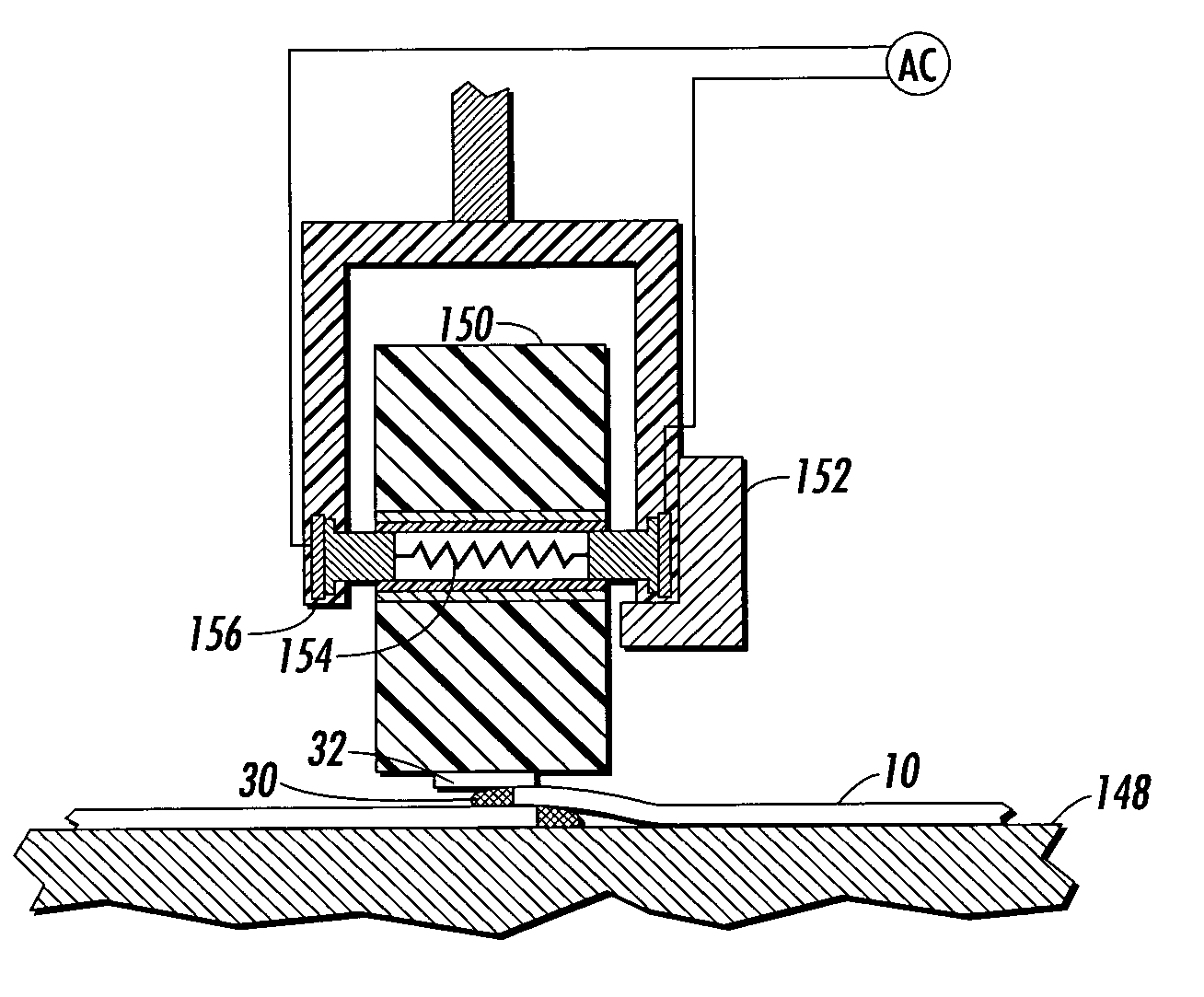
A belt seam treatment apparatus includes a support element with a smooth surface that supports the seam region of the belt and a heat and pressure source that heats a treatment strip and the belt seam region and that forces the treatment strip against the belt seam region. The support element can be a tube over which the belt hangs and can include a vacuum belt hold system that secures the seam region against the tube during treatment. The heat and pressure source can be a heated pressure bar engaging the entire seam region or a heated pressure wheel traversing the seam region of the entire belt width.

Description

[0001] This is a divisional of U.S. application Ser. No. 10 / 063,974, filed May 30, 2002 by the same inventors, and claims priority therefrom. This divisional application is being filed in response to a restriction requirement in that prior application.[0002] This application is related to U.S. patent application Ser. No. 10 / 063,971 (Attorney Docket No. D / A2002), entitled IMPROVED FLEXIBLE IMAGING MEMBER SEAM TREATMENT, U.S. patent application Ser. No. 10 / 063,973 (Attorney Docket No. D / A2002Q1), entitled FLEXIBLE IMAGING MEMBER SEAM TREATMENT ARTICLE AND PREPARATION METHOD THEREOF, and U.S. patent application Ser. No. 10 / 063,972 (Attorney Docket No. D / A2002Q), entitled FLEXIBLE IMAGING MEMBER SEAM TREATMENT APPARATUS, all filed on May 30, 2002, the disclosures of which are hereby incorporated by reference in their entirety. In addition, this application is related to U.S. patent application Ser. No. 09 / 428,932, filed on Oct. 28, 1999 in the names of Yu et al. and entitled SEAM STRESS...

Claims


Application Information

Patent Timeline
Patent Type & Authority Applications(United States)
IPC IPC(8): G03G5/10G03G5/14G03G5/147
CPCB29C65/1412B29C66/8227B29C65/18B29C65/305B29C66/1122B29C66/4324B29C66/49B29C66/723B29C66/81423B29C66/8362G03G5/10G03G5/104G03G5/142G03G5/14713G03G5/14756G03G5/14791G03G5/14795B29C65/1458B29C65/1658B29C65/1619B29C65/7847B29C66/4322B29C65/1635B29C65/1654B29C65/1696B29C66/1282B29C66/12841B29C66/71B29C66/72321B29C66/73117B29C66/73921B29C66/8122B29C66/8161B29C66/8221B29C66/855B29C66/91411B29C66/91943B29L2031/709B29K2827/18B29K2879/08B29K2079/08B29K2067/003B29K2067/00
Inventor YU, ROBERT C.U.
Owner XEROX CORP
Learn More