Orthopedic implant and method of making metal articles
a technology of orthopedic implants and metal articles, applied in the field of orthopedic implants, can solve the problems of reduced stress normally felt by the bone adjacent to the implant, reduced size and strength, and reduced stress shielding
- Summary
- Abstract
- Description
- Claims
- Application Information
AI Technical Summary
Benefits of technology
Problems solved by technology
Method used
Image
Examples
example 1
[0107] One suitable construction of an implant having a shape and design substantially in accordance with the present application is provided by the following combination of elements.
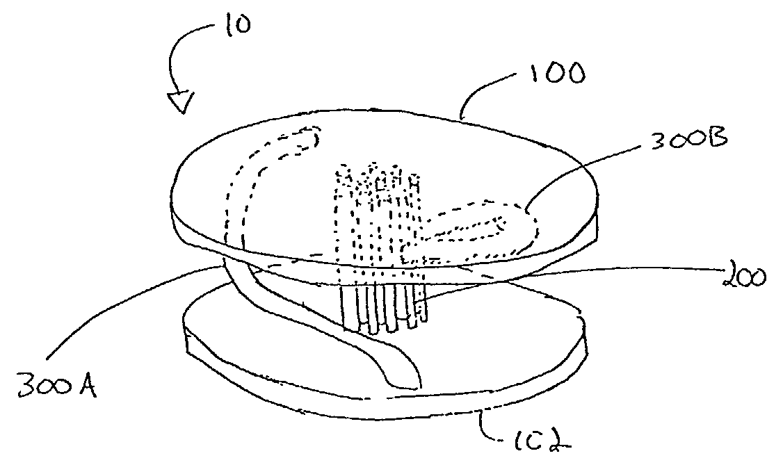
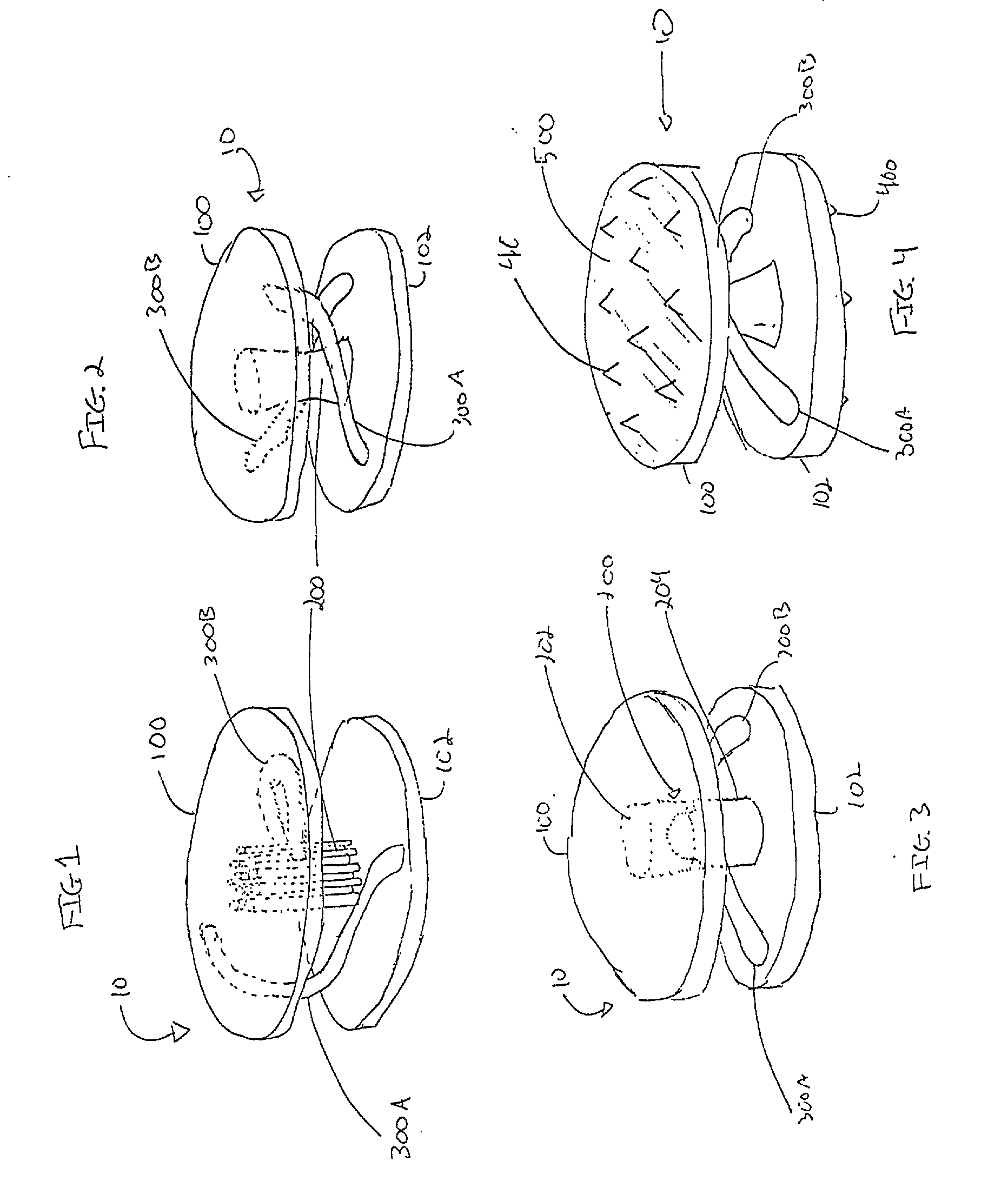
[0108] An implant 10 to be used in a spinal arthroplasty includes a first plate 100 and a second plate 102. Plates 100, 102 are substantially oval and planar and are sized to fit within a human spinal column in a space previously occupied by a disc. The outer planar surfaces of plates 100, 102 are provided with protrusions 400 consisting of teeth and a tissue ingrowth region 500 consisting of a textured surface.
[0109] Implant 10 also includes an axial support 200, between, and connecting, plates 100, 102. Axial support 200 is oriented in the center of plates 100, 102 and includes a cable incorporated at both ends to plates 100, 102. Implant 10 further includes two torsional supports 300A, 300B. Torsional supports 300A, 300B are unitarily formed with plates 100, 102 and curve around axial support 200 suc...
examples 2-7
[0111] In order to determine what values for .PHI. produce acceptable build height and preferred microstructure, a series of six examples, numbered 2-7, were made with varied parameters. For all six examples a titanium alloy containing 6% aluminum and 4% vanadium was used. The article constructed in each example was 0.0127 m.times.0.0127 m.times.0.019 m. The build parameters and resultant microstructure are shown in Table 1.
3TABLE 1 Preferred Powder Micro- Laser Speed Feed Rate .PHI. structure In Method Example Power (J / s) (m / s) (kg / s) (.times. 10.sup.6) Microstructure range Range 2 342 0.0254 0.00013 9.8 Refined .beta. grain structure .check mark. .check mark. (comprising 71.3%) 3 415 0.03387 0.000152 10.76 Refined .beta. grain structure .check mark. .check mark. (comprising 76.9%) 4 342 0.0254 0.00013 9.9 Refined .beta. grain structure .check mark. .check mark. (comprising 65.2%) 5 342 0.0339 0.00016 9.3 Large columnar .beta. grain structure, X .check mark. (refined .beta. grain s...
example 8
[0114] In order to determine the yield load, strain data and displacement of the embodiment of the application illustrated in FIGS. 19-21, the implant was tested under axial compressive loading and compressive loading 45 degrees from axial. The implant was constructed of titanium alloy containing 6% aluminum and 4% vanadium using the LENS process and had the preferred microstructure of the invention. The dimensions of the article tested were identical to that given in Table 3, except that the thickness of the swept structure was constant along its length at 2.1 mm.
[0115] Under axial testing, none of three specimens failed at loads up to 8900 N, but did incur permanent deformation on the order of 1.3 mm, or 11% of the original device height. Parts showed yielding at approximately 3560 N, exceeding the expected 3000 N yield resistance.
[0116] Under testing 45 degrees from axial, none of three specimens failed at loads up to 8900 N, but did incur permanent deformation on the order of 1....
PUM
| Property | Measurement | Unit |
|---|---|---|
| power | aaaaa | aaaaa |
| power | aaaaa | aaaaa |
| grain width | aaaaa | aaaaa |
Abstract
Description
Claims
Application Information
 - R&D
- Intellectual Property
- Life Sciences
- Materials
- Tech Scout
- Unparalleled Data Quality
- Higher Quality Content
- 60% Fewer Hallucinations
Browse by: Latest US Patents, China's latest patents, Technical Efficacy Thesaurus, Application Domain, Technology Topic, Popular Technical Reports.
© 2025 PatSnap. All rights reserved.Legal|Privacy policy|Modern Slavery Act Transparency Statement|Sitemap|About US| Contact US: help@patsnap.com


