
Echange coupling film and magnetoresistive element using the same

Active Publication Date: 2002-01-24
ALPS ALPINE CO LTD
View PDF13 Cites 29 Cited by
  • Summary
  • Abstract
  • Description
  • Claims
  • Application Information

AI Technical Summary

Benefits of technology

[0017] According to the present invention, a proper order transformation occurs in the antiferromagnetic layer through heat treatment, and an increased exchange coupling magnetic field can be generated, even when the crystal planes of the antiferromagnetic layer and the ferromagnetic layer preferentially aligned parallel to the layer surface are crystallographically identical.
[0033] By providing a seed layer below the antiferromagnetic layer, one of the crystallographically identical planes generically described as the {111} planes can be preferentially aligned parallel to the layer surface in each of the antiferromagnetic layer and the ferromagnetic layer. When the crystallographically identical planes are aligned parallel to the layer surface, an increased rate of change in resistance (.DELTA.R / R) compared to the conventional technology can be obtained.
[0037] In this invention, the antiferromagnetic material preferably further contains X', wherein X' is at least one element selected from the group consisting of Ne, Ar, Kr, Xe, Be, B, C, N, Mg, Al, Si, P, Ti, V, Cr, Fe, Co, Ni, Cu, Zn, Ga, Ge, Zr, Nb, Mo, Ag, Cd, Sn, Hf, Ta, W, Re, Au, Pb, and rare earth elements. Preferably, the antiferromagnetic material is an interstitial solid solution in which this X' is inserted to interstices in the lattice formed by X and Mn, or a substitutional solid solution in which this X' partly displaces the lattice points in the crystal lattice formed by X and Mn. In this manner, the lattice constant of the antiferromagnetic layer can be increased, and it becomes possible to prevent a one-to-one correspondence in the atomic arrangements between the antiferromagnetic layer and the ferromagnetic layer.
[0041] By setting the ratio of the components in the above-described ranges, the interface between the antiferromagnetic layer and the ferromagnetic layer can keep the lattice-mismatching state and a proper order transformation can be developed in the antiferromagnetic layer as a result of heat treatment.

Problems solved by technology

However, when the atoms of the antiferromagnetic material constituting the antiferromagnetic layer and the atoms of the soft magnetic material constituting the pinned magnetic layer exhibit a one-to-one correspondence (lattice matching) at the interface between the antiferromagnetic layer and the pinned magnetic layer, the transformation into an ordered lattice does not occur properly in the antiferromagnetic layer.
As a result, it becomes impossible to obtain an increased exchange coupling magnetic field.
When these interfaces are in a lattice-matching state during the deposition step, the antiferromagnetic layer 4 does not properly transform into an ordered lattice even after the thermal treatment.

Method used


Image

  • Echange coupling film and magnetoresistive element using the same
  • Echange coupling film and magnetoresistive element using the same
  • Echange coupling film and magnetoresistive element using the same

Examples


Embodiment Construction

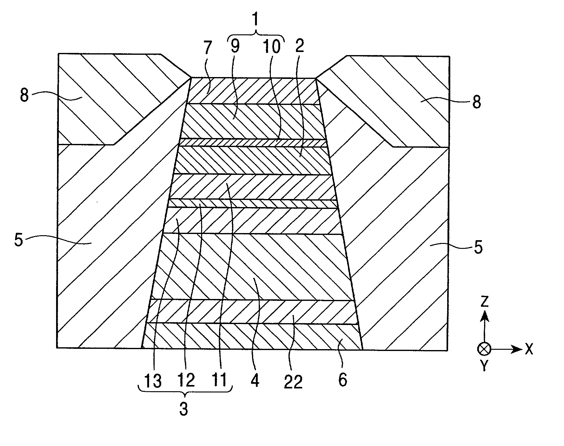
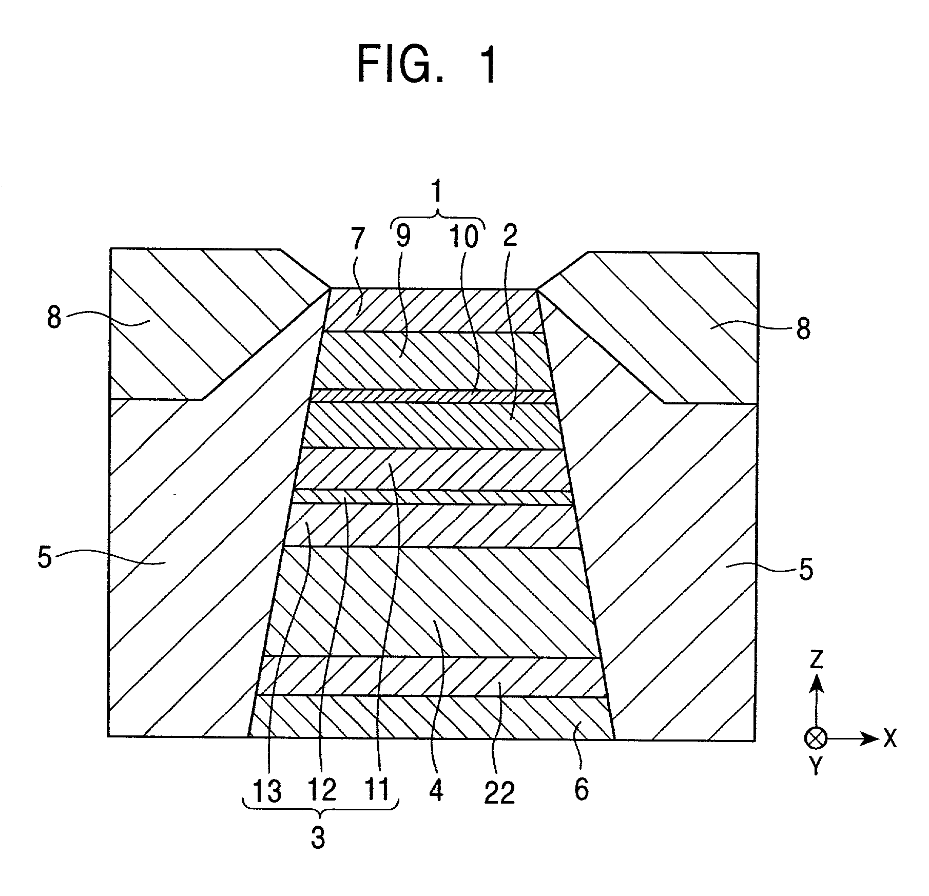
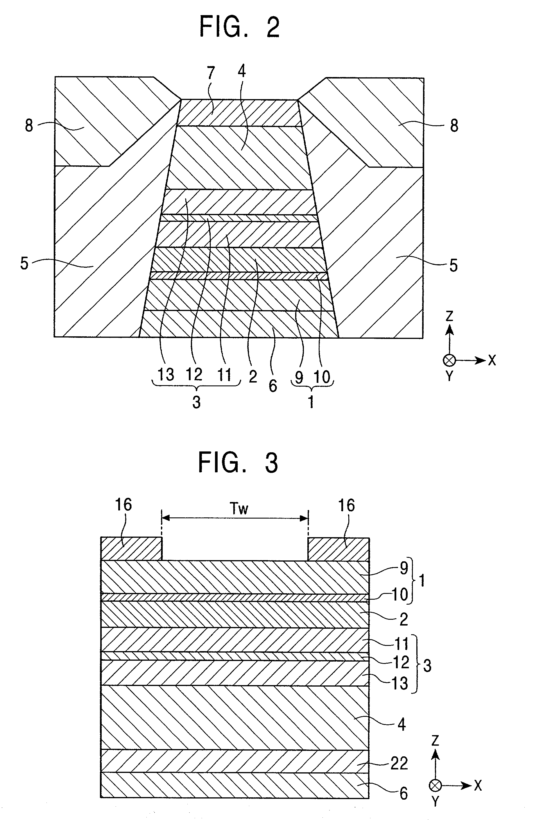
[0375] A spin-valve film having the layer configurations described below was made. The content of Pt contained in a PtMn alloy layer constituting an antiferromagnetic layer is changed so as to examine the relationship between the Pt content and the exchange coupling magnetic field (Hex).

[0376] The spin-valve film included, from the bottom: a Si substrate; an alumina layer; a Ta underlayer 3 nm in thickness; a NiFe seed layer 3 nm in thickness; a Pt.sub.xMn.sub.100-x antiferromagnetic layer 15 nm in thickness; a pinned magnetic layer composed of a Co layer 1.5 nm in thickness, a Ru layer 0.8 nm in thickness, and a Co layer 2.5 nm in thickness; a Cu nonmagnetic interlayer 2.3 nm in thickness; a free magnetic layer composed of a Co layer 1 nm in thickness and a NiFe layer 3 nm in thickness; a Cu back layer 1.5 nm in thickness; and a Ta protective layer 3 nm in thickness.

[0377] Subsequent to the deposition of the layers of the spin-valve film, the deposited layers were heat-treated at a...


PUM

PropertyMeasurementUnit
Percent by atomaaaaaaaaaa
Temperatureaaaaaaaaaa
Thicknessaaaaaaaaaa

Abstract

An exchange coupling film including an antiferromagnetic layer and a ferromagnetic layer in contact with the antiferromagnetic layer so as to generate an exchange coupling magnetic field is provided. A PtMn alloy is used as the material of the antiferromagnetic layer. Crystal planes of the antiferromagnetic layer and the ferromagnetic layer preferentially aligned parallel to the interface are crystallographically identical and crystallographically identical axes lying in these crystal planes are oriented, at least partly, in different directions between the antiferromagnetic layer and the ferromagnetic layer. Thus, a proper order transformation occurs in the antiferromagnetic layer as a result of heat treatment and an increased exchange coupling magnetic field can be obtained.

Description

[0001] 1. Field of the Invention[0002] The present invention relates to an exchange coupling film comprising an antiferromagnetic layer and a ferromagnetic layer, in which the magnetization vector of the ferromagnetic layer is oriented in a particular direction by an exchange coupling magnetic field generated at the interface between the antiferromagnetic layer and the ferromagnetic layer. The present invention is particularly directed to an exchange coupling film having a strong exchange coupling magnetic field, a magnetoresistive element (spin valve thin-film element or AMR element) employing the exchange coupling film, and a thin-film magnetic head incorporating the magnetoresistive element.[0003] 2. Description of the Related Art[0004] A spin-valve thin-film magnetic head is a type of giant magnetoresistive element (GMR) which utilizes the giant magnetoresistive effect. The spin-valve thin-film magnetic head detects a recorded magnetic field from a recording medium such as a har...

Claims


Application Information

Patent Timeline
IPC IPC(8): G01R33/09G11B5/39H01F10/12H01F10/30H01F10/32H01L43/08
CPCB82Y10/00Y10T428/12826G11B5/3903G11B5/3932G11B2005/3996H01F10/3218H01F10/3268H01F41/325H01F10/123Y10T428/265Y10T428/11Y10T428/12854Y10T428/1107Y10T428/12465Y10T428/1143Y10T428/32B82Y25/00
Inventor HASEGAWA, NAOYASAITO, MASAMICHI
Owner ALPS ALPINE CO LTD
Learn More