
Fe-Ni alloy shadow mask blank with excellent etch perforation properties and method for manufacturing the same

a technology of etch perforation and shadow mask, which is applied in the field of etch perforation mask blanks of fe-ni alloy, can solve the problems of reducing mns and other inclusions to zero, and achieve the effect of reducing the unevenness of the aperture diameter

Inactive Publication Date: 2001-12-06
JX NIPPON MINING & METALS CO LTD
View PDF0 Cites 14 Cited by
  • Summary
  • Abstract
  • Description
  • Claims
  • Application Information

AI Technical Summary

Benefits of technology

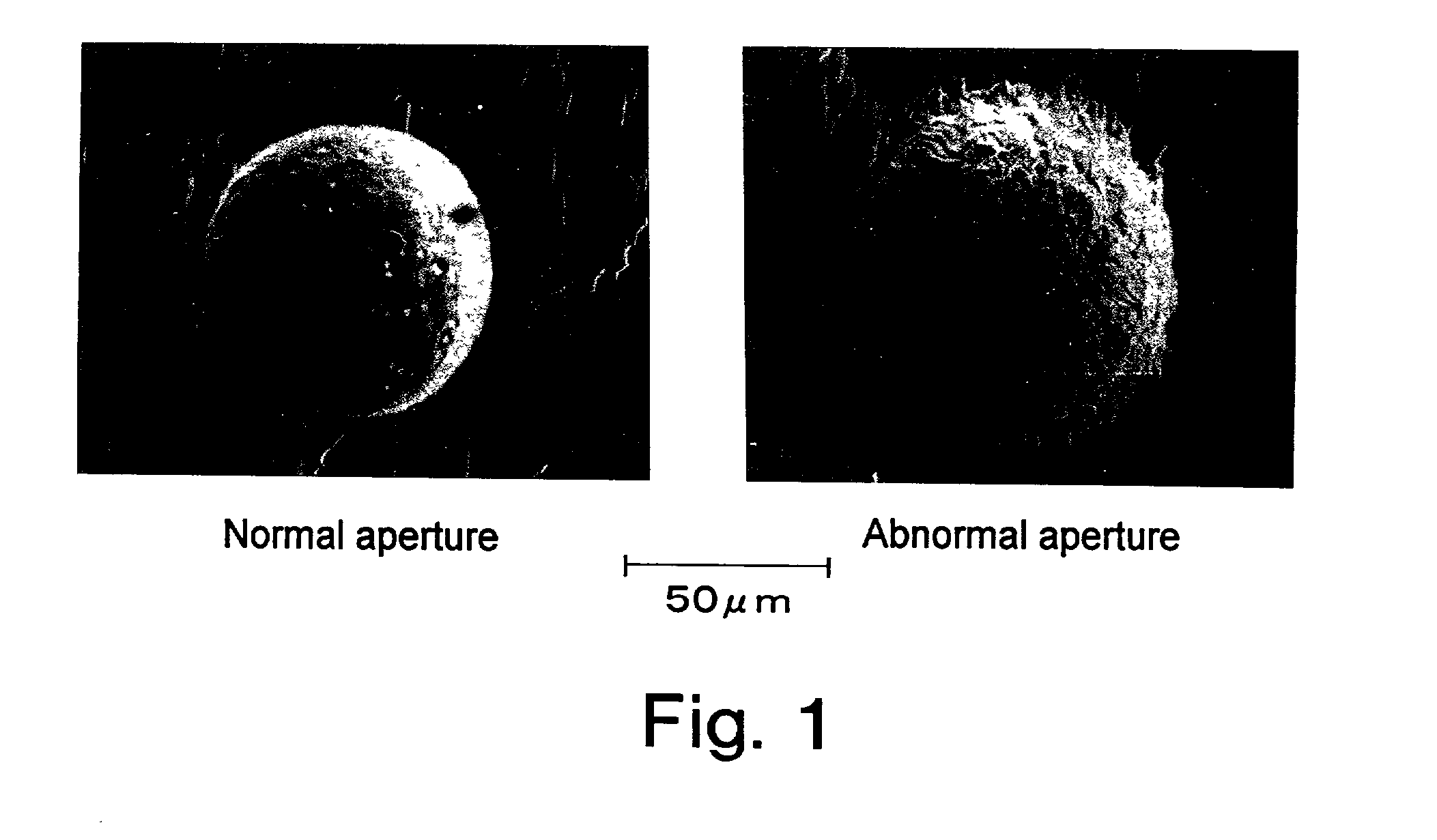
[0010] This invention is aimed at providing a shadow mask blank of Fe--Ni alloy which, in perforation by etching to form apertures for the passage of electron beams, will not have unevenness in the diameters of the apertures due to the formation of abnormal apertures, even if the etching conditions are locally varied, and is also aimed at providing a method of manufacturing the blank.
[0013] A rolled blank of Fe--Ni alloy according to this invention is usually etched to be a shadow mask, using an aqueous solution of ferric chloride. For that purpose a resist film is applied to the blank to cover the portions not to be perforated, so that only the portions to be perforated are exposed to the aqueous ferric chloride. If minute MnS particles are present in the portions to be perforated, they act as starting points of corrosion, accelerating the etching of the base metal. If no MnS is present in any of the portions to be perforated, all the portions are similarly etched, resulting in no unevenness of aperture diameter. In actual production on an industrial scale, however, difficulties are involved in reducing MnS and other inclusions to zero; in some portions to be perforated there are MnS particles that serve as corrosion-starting points with a certain probability. The portions to be perforated that have such corrosion-starting points initiate etching faster than the neighboring portions free from the corrosion-starting points, producing apertures with larger diameters. Since the portions to be perforated that have the starting points begin etching before the neighboring portions that do not have the starting points, the portions with the starting points electrochemically act as anodes, while the portions without the starting points act as cathodes. In this case the difference between the rates of corrosion becomes more pronounced and the difference between the diameters of etched apertures is greater too. If the blank contains minute MnS particles at a level beyond a certain density, the MnS particles are uniformly present in all the portions to be perforated, precluding any unevenness of aperture diameter.
[0066] Under the high-temperature short time annealing conditions it is difficult to cause positive precipitation of MnS. However, the solid solution of MnS can be prevented by restricting the highest achievable temperature of annealed material to or below 900.degree. C. (the boundary temperature between MnS solid solution and precipitation). On a continuous annealing line the material temperature does not reach the atmosphere temperature inside the furnace, and the attainable material temperature varies with both the atmosphere temperature inside the furnace and the rate at which the material is passed through the furnace. Thus, the attainable material temperature should be evaluated in terms of the actually measured temperature of the material rather than the atmosphere temperature inside the furnace. Exact measurement of the material temperature is extremely difficult, however. In view of this, we investigated the relation between the atmosphere temperature inside the furnace and the number of MnS particles from 50 to 1,000 nm in diameter that are left after the annealing under conditions that the mean grain size after the annealing is adjusted to 30 .mu.m. As a result it was found that if the furnace atmosphere temperature is adjusted to 1,100.degree. C. or below, the number of MnS particles remain practically unchanged before and after the annealing. It was learned from this result that, when the grain size after the annealing is adjusted to 5 to 30 .mu.m, the attainable material temperature does not exceed 900.degree. C. if the atmosphere temperature inside the furnace is set to 1,100.degree. C. or below. On the other hand, when the furnace temperature was below 850.degree. C., the rate at which the material was passed through the furnace to obtain recrystallized grains 5 .mu.m or more in diameter was slowed down, seriously decreasing the production efficiency.
[0067] From the foregoing it was found that if the atmosphere temperature inside the furnace is set to the range of 850 to 1,100.degree. C. when annealing a Fe--Ni alloy using a continuous annealing line, recrystallized grains with mean diameters in the range of 5 to 30 .mu.m can be obtained without losing the MnS particles from 50 to 1,000 nm in diameter and decreasing the production efficiency.
[0108] By etching the above blank to form the apertures for the passage of electron beams, there is provided a shadow mask blank formed with electron beam-passage apertures with reduced unevenness of aperture diameters due to the presence of abnormal apertures.

Problems solved by technology

In actual production on an industrial scale, however, difficulties are involved in reducing MnS and other inclusions to zero; in some portions to be perforated there are MnS particles that serve as corrosion-starting points with a certain probability.

Method used


Image

  • Fe-Ni alloy shadow mask blank with excellent etch perforation properties and method for manufacturing the same
  • Fe-Ni alloy shadow mask blank with excellent etch perforation properties and method for manufacturing the same
  • Fe-Ni alloy shadow mask blank with excellent etch perforation properties and method for manufacturing the same

Examples


example 5

(Annealing not Accompanied with Recrystallization)

[0133] With regard to the method of effecting MnS precipitation by carrying out an annealing not accompanied with recrystallization after the final rolling (rolling III), the relations between the annealing conditions (annealing method, temperature inside the annealing furnace, and retention time in the furnace) and the number of etched holes formed upon immersion in a 3% nitric acid-ethyl alcohol solution were studied. The method of measuring the etched holes was the same as used in Example 1. The resulting structures were also observed in the same way. In this test, 200 mm-thick slabs of the same compositions as in Example 1 were cold rolled (final cold rolling, rolling III) to a thickness of 0.1 mm under the same conditions as for No. 6 in Example 1, and annealed. The results are given in Table 5. A comparison between batch and continuous annealing operations shows that batch annealing produces increased numbers of etched holes.

5T...


PUM

PropertyMeasurementUnit
Temperatureaaaaaaaaaa

Abstract

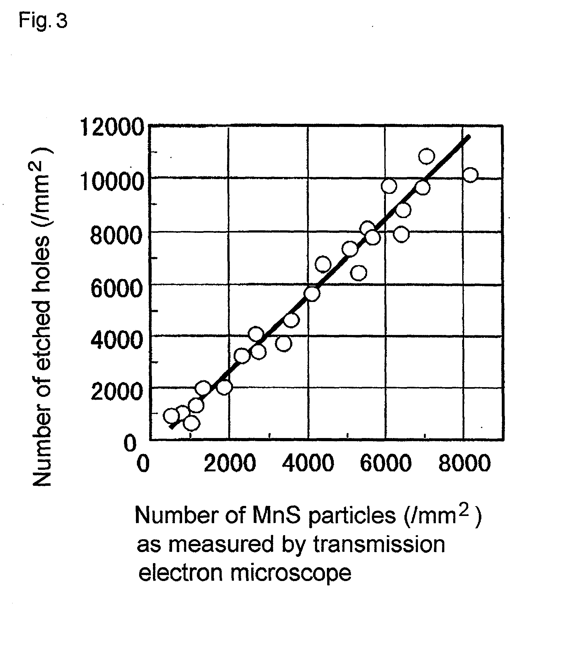
A shadow mask blank of Fe-Ni alloy which exhibits excellent uniformity of diameter of apertures formed by perforation with etching for the passage of electron beams, consisting of 34-38% Ni, 0.05-0.5% Mn, 4-20 ppm S, and the balance Fe and no more than specified limits of C, Si, Al, and P, with MnS inclusions 50-1,000 nm in diameter dispersed at the density of at least 1,500 / mm2 or simply with etched holes 0.5-10 mum in diameter emerging at the density of at least 2,000 / mm2 when the blank is immersed in a 3% nitric acid-ethyl alcohol solution at 20° C. for 30 seconds. A method of manufacturing the blank comprises hot rolling of a slab of the Fe-Ni alloy, cooling, recrystallization annealing, cold rolling, etc. under controlled conditions: e.g., hot rolling the slab at 950-1,250° C. to 2-6 mm thick, cooling the stock in the range of 900-700° C. at the rate of 0.5° C. / second, continuously passing the stock through a heating furnace at 850-1,100° C. for recrystallization annealing to adjust the mean diameter of the recrystallized grains to 5-30 mum, and performing the cold rolling before the final recrystallization annealing at a reduction ratio of 50-85% and the final cold rolling at a reduction ratio of 10-40%.

Description

[0001] This invention relates to a Fe--Ni alloy blank for use in making a shadow mask by fine etching, and more specifically to a Fe--Ni alloy shadow mask blank which, when perforated by fine etching to form apertures through which electron beams pass, can improve the unevenness of aperture diameters due to the presence of irregular apertures and can provide electron beam apertures of uniform diameter and also relates to a shadow mask blank which has been formed with apertures for the passage of electron beams having improved unevenness of aperture diameters due to the presence of irregular apertures. The invention further relates to a method for manufacturing a Fe--Ni alloy blank with such properties.[0002] In the following description the concentrations of alloy components are given on the basis of mass proportions (%=mass percentage; ppm=mass proportion).[0003] As material of shadow masks for color picture tubes, mild steel has been commonly used. The mild steel, however, present...

Claims


Application Information

Patent Timeline
IPC IPC(8): C21D8/02C22C38/00C21D9/46C22C38/04C22C38/08C23F1/00H01J29/07
CPCC21D8/0236C21D8/0278C22C38/004C22C38/04C22C38/08H01J2229/0733C21D8/0205C21D8/0226C23F1/02H01J29/07
Inventor HATANO, TAKAAKIKITA, YOSHIHISA
Owner JX NIPPON MINING & METALS CO LTD
Learn More