
Metal-air fuel cell battery system employing a plurality of moving cathode structures for improved volumetric power density

a fuel cell battery and moving cathode technology, applied in the direction of primary cell maintenance/service, cell components, secondary cell servicing/maintenance, etc., can solve the problems of inability to generate large amounts of electrical power from prior art fcb systems, and difficulty in producing fcb systems with high volumetric power density characteristics measured

Inactive Publication Date: 2001-07-12
REVEO
View PDF0 Cites 30 Cited by
  • Summary
  • Abstract
  • Description
  • Claims
  • Application Information

AI Technical Summary

Benefits of technology

[0009] Accordingly, it is a primary object of the present invention to provide an improved metal-air fuel cell battery (FCB) system which avoids the shortcomings and drawbacks of prior art systems and methodologies.
[0012] Another object of the present invention, is to provide such a FCB system, wherein the metal-fuel tape, ionically-conducting medium and cathode structures are moved at substantially the same velocity at points where the ionically-conducting medium contacts the cathode structures and the metal-fuel tape during discharging and recharging operations, thereby minimizing the generation of frictional (e.g. shear) forces among the cathode structures, ionically-conducting medium and metal-fuel tape in the system, and thus reduce the amount of electrical power required to drive the tape transport mechanism, the shedding of metal-oxide particles from metal-fuel tape which can become embedded within the cathode structures, and the likelihood of damage or destruction of the cathode structures and metal-fuel tape.
[0031] Another object of the present invention is to provide such a system, wherein the metal-fuel tape is realized in the form of thin zinc tape, zinc power mixed with a binder and carried on a polyester substrate, or zinc powder impregnated within the substrate itself. Another object of the present invention is to provide a system, wherein the metal-fuel tape, cathode structures and ionically-conductive medium are moved relative to each other so that frictional (e.g. shear) forces generated among the metal-fuel tape ionically-conductive medium and cathode structures are substantially reduced.
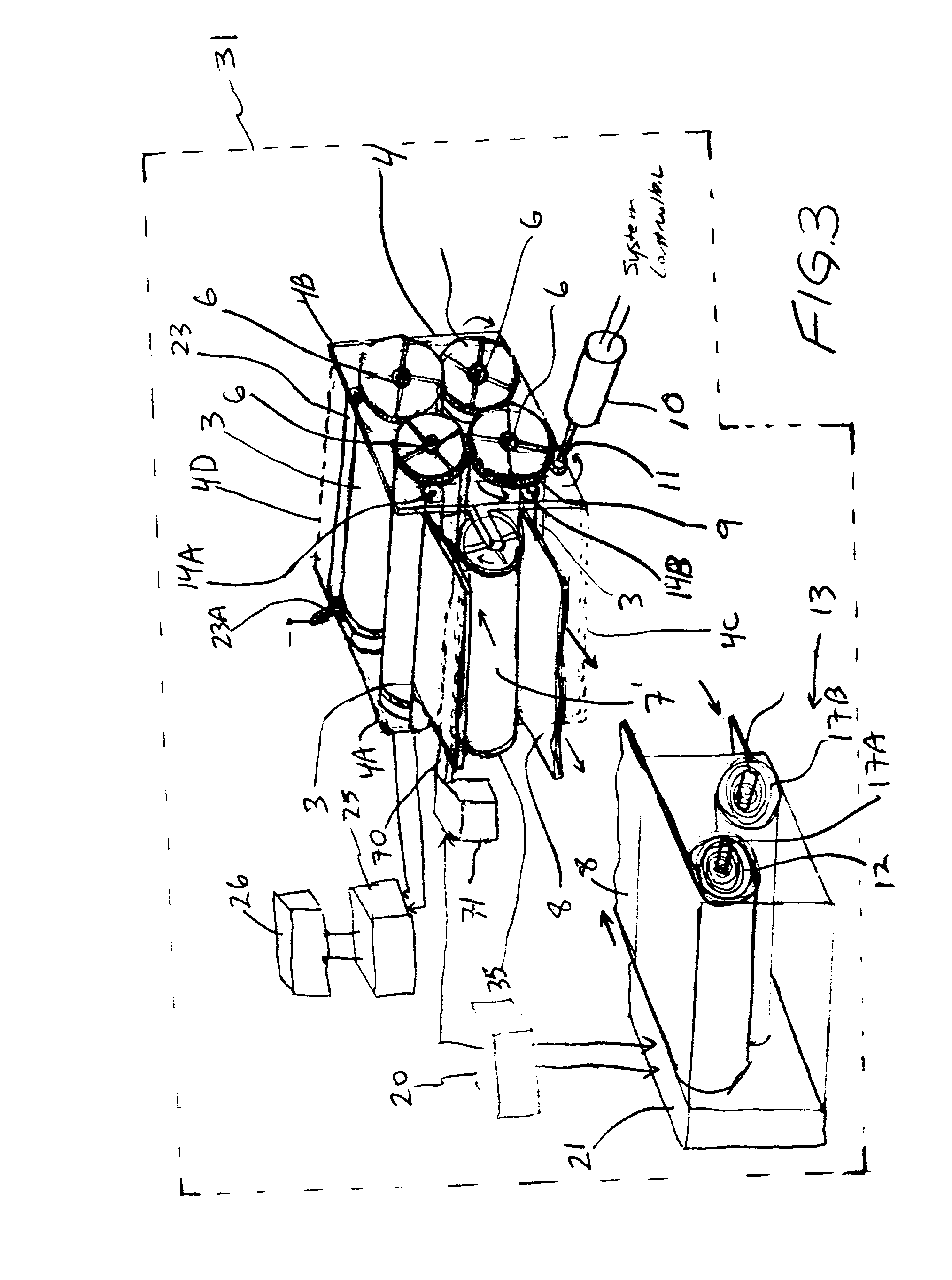
[0063] FIG. 12 is a seventh illustrative embodiment of the FCB system, wherein multiple streams of metal-fuel tape are simultaneously transported over a plurality of cathode belt structures, and simultaneously taken up on a take-up reel in order to reduce bending of metal-fuel tape during system operation.

Problems solved by technology

However, when using such prior art technology it has been very difficult to produce FCB systems having high volumetric power density characteristics measured, for example, in kilowatts / cm.sup.3.
Consequently, it has not been possible to generate large amounts of electrical power from prior art FCB systems occupying relatively small volumes of physical space.

Method used


Image

  • Metal-air fuel cell battery system employing a plurality of moving cathode structures for improved volumetric power density
  • Metal-air fuel cell battery system employing a plurality of moving cathode structures for improved volumetric power density
  • Metal-air fuel cell battery system employing a plurality of moving cathode structures for improved volumetric power density

Examples


Embodiment Construction

Of the Present Invention should be read in conjunction with the accompanying Drawings, wherein:

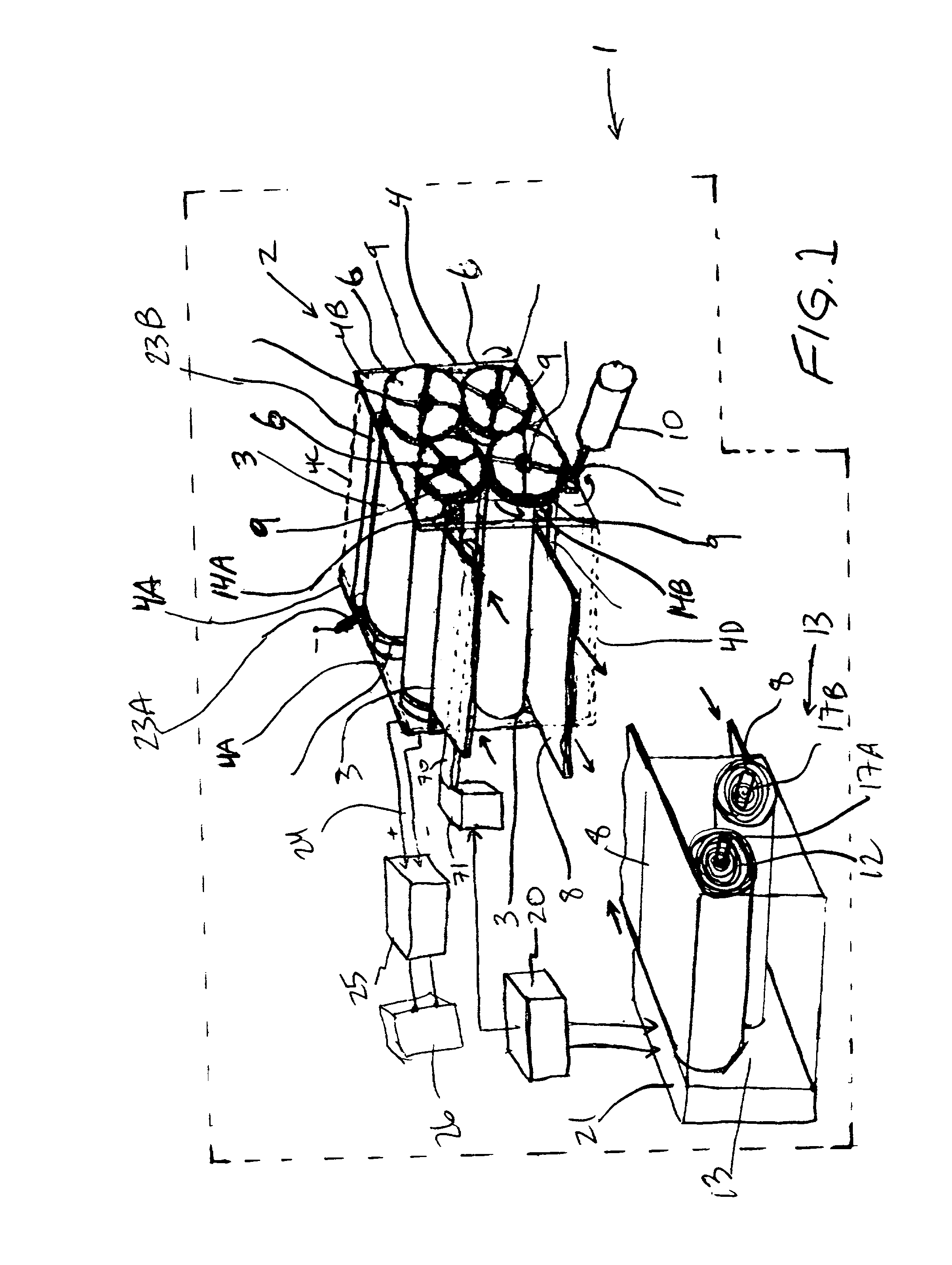
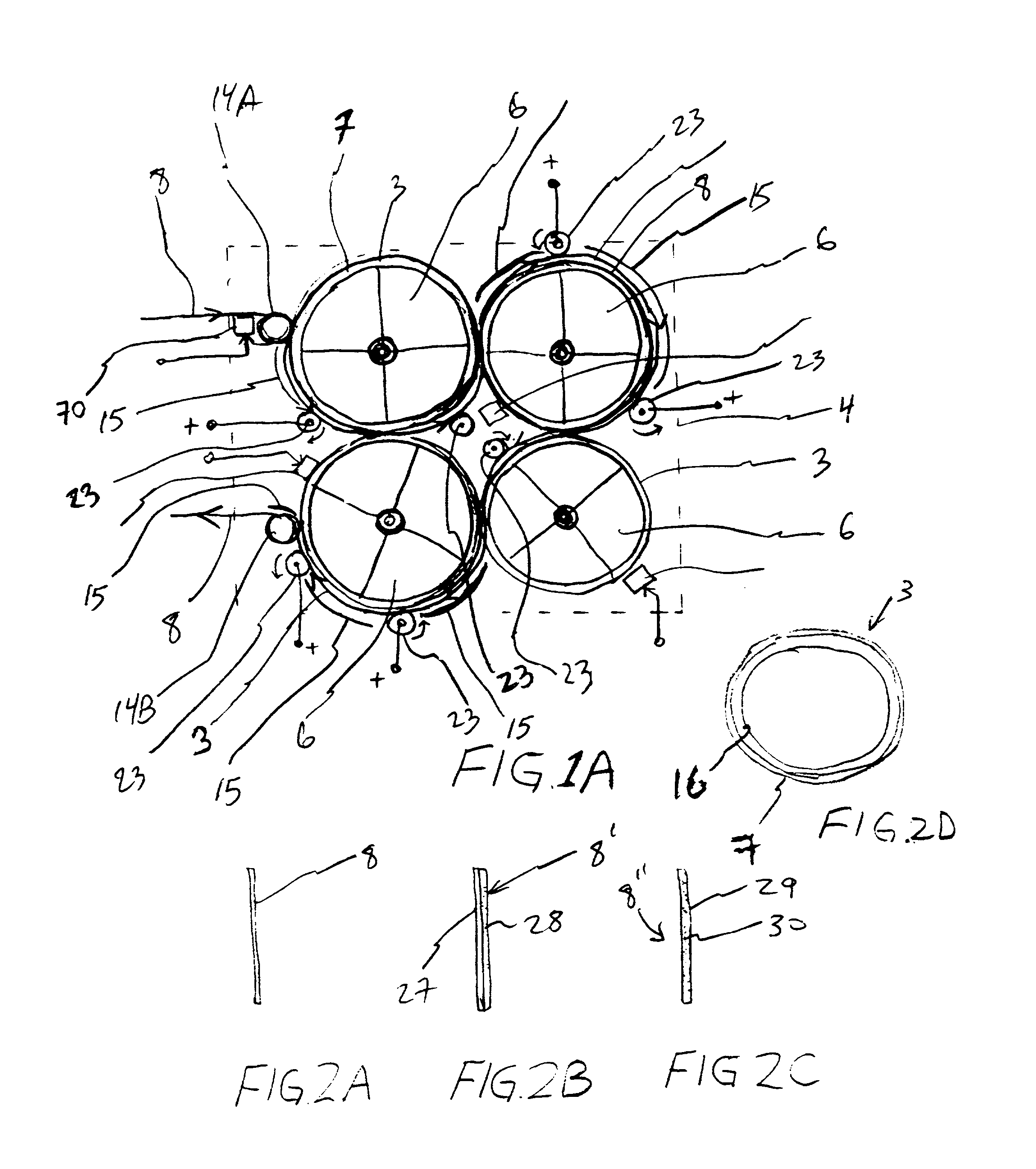
[0035] FIG. 1A is a schematic representation of a first illustrative embodiment of the metal-air fuel-cell battery (FCB) system of the present invention, wherein a plurality of cathode cylinders are rotatably mounted within a compact support fixture (i.e. housing), and metal-fuel tape stored within a cassette-type cartridge is transported over the surface of the rotatably mounted cathode cylinders with an ionically-conductive medium disposed between the metal-fuel tape and cathode cylinders at the locus of points at which the ionically-conductive medium contacts each cathode cylinder and metal-fuel tape;

[0036] FIG. 1B is an elevated side view of the FCB system depicted in FIG. 1, showing the path of travel of the metal-fuel tape through the compact support fixture, and the location of tape path guides and cathode and anode contacting elements mounted therewithin, wherein the ionically-cond...


PUM


Abstract

In an air-metal fuel cell battery (FCB) system, wherein a plurality of movable cathode structures are mounted within a compact housing through which metal-fuel tape is transported along a predetermined path while an ionically-conductive medium is disposed between the metal-fuel tape and each movable cathode structure at points of contact. In illustrative embodiments, the movable cathode structures are realized as rotatable cathode cylinders, and transportable cathode belts. The ionically-conductive medium is realized as a solid-state ionically-conductive film applied to the cathode structures and / or metal-fuel tape, as well as ionically-conductive belt structures transported at the same velocity as corresponding cathode structures (e.g. cathode cylinders or belts) at the locus of points at which the ionically-conductive medium contacts the moving cathode structure and the moving metal-fuel tape. By virtue of the present invention, the volumetric power density characteristics of FCB systems can be significantly improved, while the likelihood of damage to the cathode structures and metal-fuel tape is substantially reduced.

Description

RELATED CASES[0001] This is a Continuation-in-Part of: copending application Ser. No. 09 / 074,337 entitled "Metal-Air Fuel-Cell Battery Systems" filed May 7, 1998; and copending application Ser. No. 08 / 944,507 entitled "High-Power Density Metal-Air Fuel Cell Battery System" by Sadeg Faris, et al. filed Oct. 6, 1997, said application being assigned to Reveo, Inc. and incorporated herein by reference in its entirely.BACKGROUND OF INVENTION[0002] 1. Field of Invention[0003] The present invention relates to metal-air fuel cell battery (FCB) systems designed to produce electrical power from metal-fuel tape transported over a plurality of moving cathode structures in order to increase the volumetric power density characteristics of the system.[0004] 2. Brief Description of the Prior Art[0005] In copending U.S. application Ser. No. 08 / 944,507 entitled "High-Power Density Metal-Air Fuel Cell Battery System", Applicants disclose several types of novel metal-air fuel cell battery (FCB) systems...

Claims


Application Information

Patent Timeline
IPC IPC(8): H01M2/02H01M2/12H01M2/16H01M2/36H01M2/38H01M4/00H01M4/02H01M4/42H01M4/70H01M4/86H01M6/50H01M8/04H01M8/10H01M8/18H01M8/22H01M10/42H01M10/44H01M10/46H01M10/48H01M12/06H01M12/08H02J7/00
CPCH01M2/1673H01M4/42H01M4/8605H01M6/5011H01M8/184H01M8/186H01M8/22H01M10/4214H01M10/44H01M12/06H01M12/08H01M2004/024H01M2300/0085H02J7/00Y02E60/522Y02E60/528Y02E60/10Y02E60/50H01M50/46
Inventor FARIS, SADEG M.TSAI, TSEPINLEGBANDT, THOMAS J.YAO, WAYNECHEN, MUGUO
Owner REVEO
Learn More