Multipolar switch
a multi-polar switch and switch technology, applied in the direction of emergency contacts, switch side locations, seperate bridge contact, etc., to achieve the effect of improving the tactile
- Summary
- Abstract
- Description
- Claims
- Application Information
AI Technical Summary
Benefits of technology
Problems solved by technology
Method used
Image


Examples
first embodiment
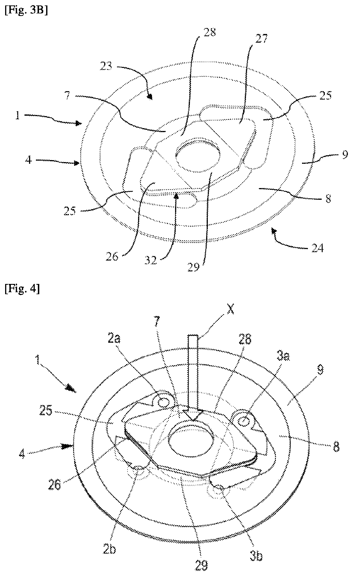
[0054] shown in FIGS. 3A, 3B, 4, and 5, the multipolar switch 1 comprises a part made from an electrically conducting material 4 that advantageously has the form of a metal cup, allowing a user to actuate the switch. This type of metal cup is known per se in the field of electronic devices.
[0055]The switch shown in FIGS. 3A, 3B, 4, and 5 is a switch of a LED. The switch according to the first embodiment is not however limited to a LED switch and the operation of such a LED shall not be described in the present text.
[0056]The cup 4 is advantageously preformed. It has the shape of a disc, comprising a central portion 7, an intermediate portion 8 which extends around the central portion, and a peripheral portion 9 which extends around the intermediate portion. The invention is not however limited to a cup that has the shape of a disc, and other shapes are suitable according to the type of switch, for example a square, rectangular or triangular shape.
[0057]The cup 4 is dome-shaped at th...
second embodiment
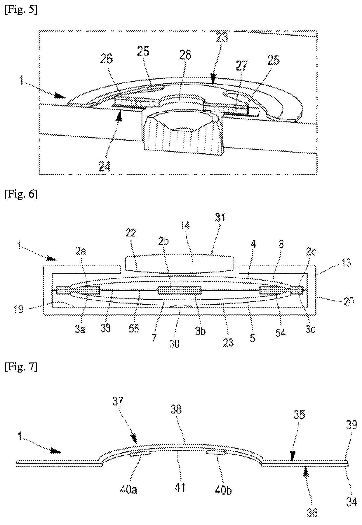
[0081] shown in FIG. 6, the multipolar switch 1 comprises two metal cups, of which a first cup 4 and a second cup 5.
[0082]The metal cups 4, 5 are similar to those described in the first embodiment, except that the latter are preferably solid. Indeed, it is not necessary to make cuts in the cups to allow for the operation of the switch according to this second embodiment.
[0083]The first and the second cup 4, 5 are arranged one above the other, facing, the first cup 4 being located above the second cup 5.
[0084]The two cups 4, 5 are housed in a housing 13 provided with a bottom 19 delimited laterally by a lateral surface 20 that extends from the bottom 19 by moving away from the bottom. The peripheral portion 8 of the two cups 4, 5 is fixed to the housing.
[0085]The two cups 4, 5 are arranged in such a way that their convex curvature is separated from the median plane that extends between the two cups. The upper face of the first cup is therefore directed towards the top in the plane of...
third embodiment
[0104] shown in FIG. 7, the multipolar switch 1 comprises an electrically insulating thermoformed film 34.
[0105]Such a thermoformed film 34 can be manufactured by heating the material so as to soften it, then by forming the material that has thus become ductile so that the latter takes a predefined shape, and retains it after cooling to ambient temperature.
[0106]Alternatively, the thermoformed film 34 can be cold-formed, i.e. at ambient temperature.
[0107]The material of the thermoformed film preferably comprises a thermoplastic polymer suitable for being formed by thermoforming.
[0108]The thermoplastic polymer is preferably chosen from: polystyrene (PS), polyethylene (PE), polypropylene (PP), polycarbonate (PC), acrylonitrile butadiene styrene (ABS), polyvinyl chloride (PVC), polymethyl methacrylate (PMMA), and mixtures thereof, present in the form of homopolymers or copolymers.
[0109]The thermoformed film 34 comprises an upper face 35 and a lower face 36 opposite the upper face with ...
PUM
 Abstract
Description
Claims
Application Information
 - R&D
- Intellectual Property
- Life Sciences
- Materials
- Tech Scout
- Unparalleled Data Quality
- Higher Quality Content
- 60% Fewer Hallucinations
Browse by: Latest US Patents, China's latest patents, Technical Efficacy Thesaurus, Application Domain, Technology Topic, Popular Technical Reports.
© 2025 PatSnap. All rights reserved.Legal|Privacy policy|Modern Slavery Act Transparency Statement|Sitemap|About US| Contact US: help@patsnap.com