Secured keypad for an electronic data-entry device

a keypad and data entry technology, applied in emergency protective devices, instruments, computing, etc., can solve the problems of not being secured, more difficult to obtain, and relatively easy for malicious individuals to access

Active Publication Date: 2020-06-02
BANKS & ACQUIRERS INT HLDG
View PDF7 Cites 0 Cited by
  • Summary
  • Abstract
  • Description
  • Claims
  • Application Information

AI Technical Summary

Benefits of technology

[0017]In this way, the keypad according to the invention is more secured than the conventional keypads inasmuch as the key-press detection contacts are no longer immediately accessible beneath the associated key but are disposed on the internal face of a flexible printed-circuit board. In other words, these contacts are kept situated beneath the flexible printed-circuit board which then forms a protection that counters direct access to these contacts from above the keypad. The flexible printed-circuit board also comprises a connecting portion that forms a fold beneath the internal face. Thus, the fold forms a protection that counters access to the contacts from at least one side of the keypad or even all sides in certain embodiments. Finally, the element to which the flexible printed-circuit board is connected—typically the motherboard of the electronic data-entry device—naturally forms a complementary protection that counters access to the contacts of the keys from beneath the keypad. In this way, the flexible printed-circuit board forms, for example with the motherboard to which it is connected, a protective enclosure that completely encloses—and therefore protects—the sensitive zones of the keypad where pieces of confidential data are likely to travel.
[0019]In this way, the securing of the keypad is further increased without its being necessary to resort to a specific complementary protective printed-circuit board (as is the case for example in the prior-art solution illustrated with reference to FIG. 1b already described, in which the use of a complementary protective printed-circuit board 40 proves to be necessary). Indeed, the flexible printed-circuit board of the proposed technique is a multi-layered printed-circuit board, at least a dual-face board, the internal face of which is used to implement the key-press detection circuit and possibly other complementary circuits, and the external face of which, and / or at least one layer buried in the flexible printed-circuit board, is totally covered by these protective elements. Thus, the proposed solution does away with the use of a specific complementary protective printed-circuit board, thus enabling the implementing of a keypad having a more compact structure while at the same time reducing costs, without in any way reducing the level of security.
[0021]Thus, a well-known interconnection element—in this case a low-cost, commercially available deformable dome—is ingeniously positioned in an inverted position relative to the classic prior-art solution. Compared with the classic assembly (i.e. non-inverted assembly) of the domes described in the prior-art solutions, the inverted assembly according to the proposed technique provides enhanced mechanical strength to the keys of the keypad, increased stability to the keypad as a whole and a better tactile effect for the user when he presses a key.
[0023]Thus, the flexible printed-circuit board undergoes relatively little stress from the deformation undergone through an action of pressing a key because the deformable domes and the keys are shaped and sized so that a relatively large surface area of the flexible printed-circuit board is pressed. The result of this is that the protective elements that may be integrated into the flexible printed-circuit board are also less stressed during the deformation of the flexible printed-circuit board. In this way, the wear and tear of the protective elements, especially when they take the form of protective grid elements, is limited as compared with the prior-art solutions. The risks of inaccurate and untimely detections of intrusion, which would result from the premature deterioration of the protective grid elements even when the keypad is being put through quite normal use, are therefore reduced.
[0027]Such a configuration, combined with the fact that the domes are inverted, releases space on the motherboard as compared with the prior-art solutions. Indeed, the motherboard then acts simply as a mechanical counter-pressure element and there is no longer any need to integrate therein the pairs of contacts associated with the keys of the keypad, and this releases space. Besides, the surfaces of the motherboard reserved to act as counter-pressure zones are smaller than in the prior-art solutions inasmuch as it is now the peaks of the domes—hence their narrowest part—and no longer their base that presses on the motherboard, giving rise to even greater gain in space.

Problems solved by technology

Not all the electronic data-entry devices however are provided with a touchscreen, and there are many situations in which the use of a physical keypad continues to be the most appropriate solution, for example in order to control the production costs of the data-entry device (a touchscreen is costly) or again because a physical keypad offers natural tactile feedback to the user (who can literally touch and feel the keys and the pressure beneath his fingers, an effect more difficult to obtain with a virtual keypad).
One drawback of a keypad as described with reference to FIG. 1a is that it is not secured: indeed, it is relatively easy for a malicious individual to access the signals for detecting key-pressing actions, for example by introducing probes at the contacts 203 or at the electrical tracks present on the connection printed-circuit board 20.
This poses a problem of security, especially when such a keypad is used to enter sensitive data.
Thus, these zones in which the pairs of contacts 203 are situated constitute points of weakness of the keypad because they are not protected and therefore easily accessible to a malicious individual.
It is however costly because it requires the use of a complementary protective printed-circuit board (the flexible printed-circuit board 40) that is different from the connection printed-circuit board 20 to provide efficient securing of the keypad.

Method used


Image

  • Secured keypad for an electronic data-entry device
  • Secured keypad for an electronic data-entry device

Examples


Embodiment Construction

[0039]General Principle

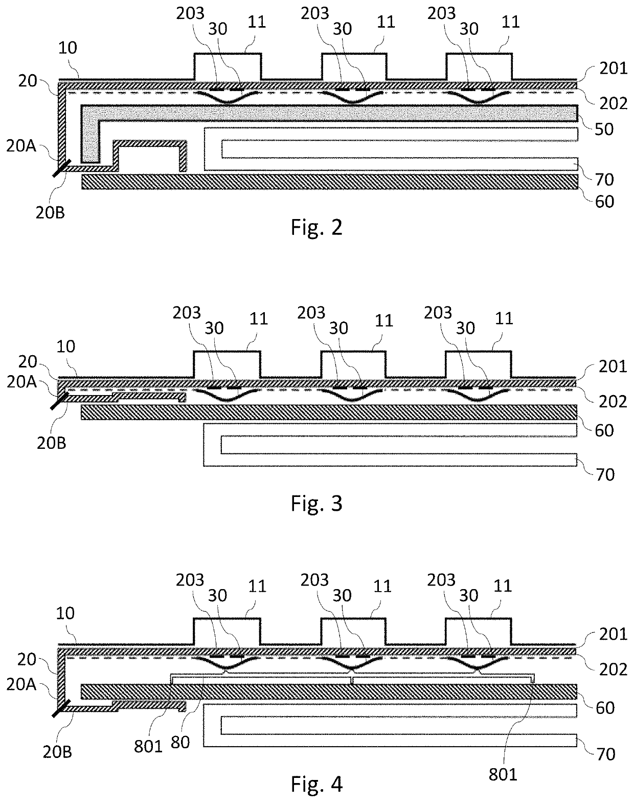
[0040]The general principle of a keypad according to the proposed technique is presented with reference to FIG. 2. It must be noted however that this general principle could equally well be presented with reference to FIG. 3 or 4. FIGS. 2, 3 and 4 illustrate different embodiments of a keypad, the securing of which relies on one and the same general principle. Throughout the description, elements of a same nature are identified by a same numerical reference in the figures.

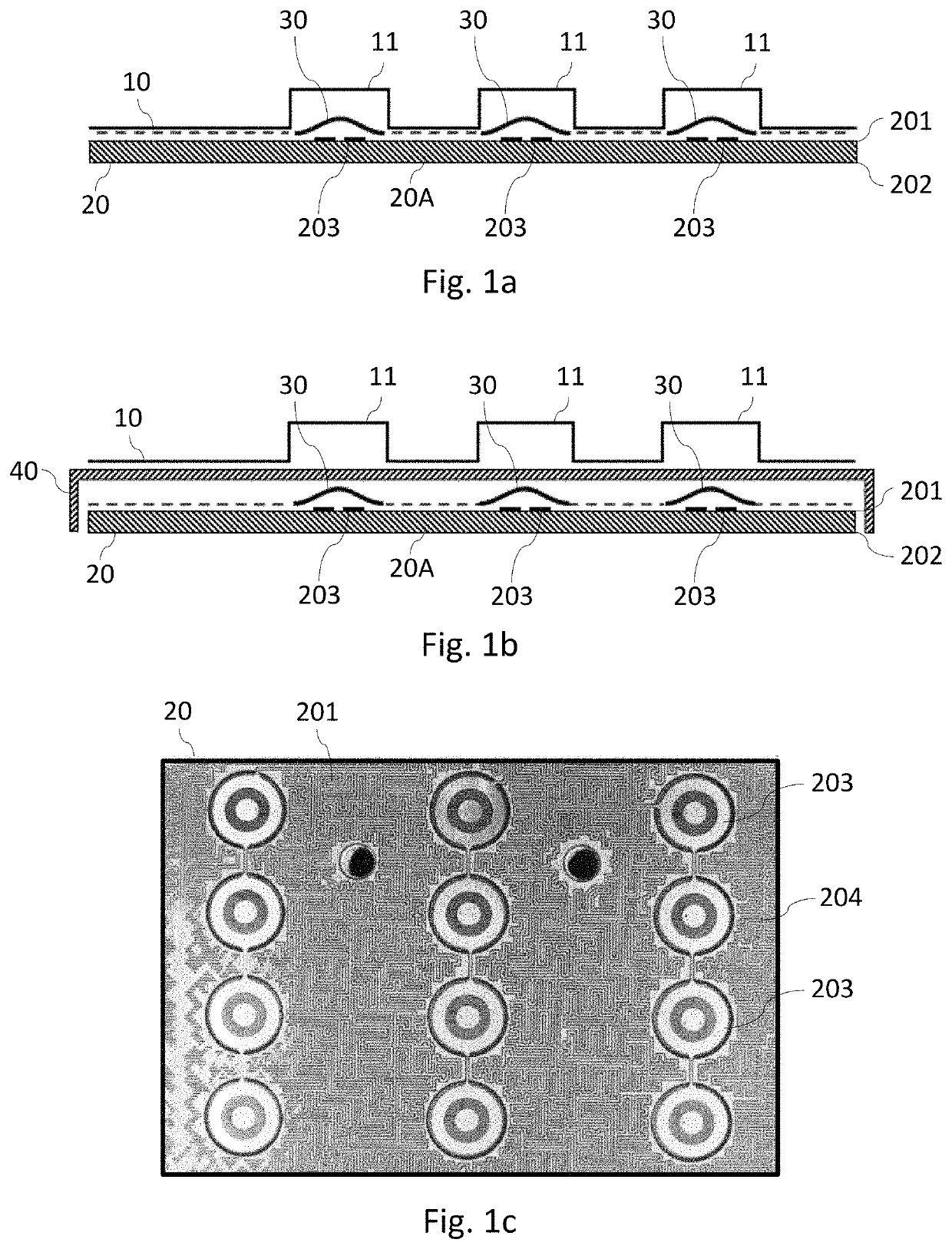
[0041]The keypad according to the proposed technique has many structural characteristics in common with prior-art keypads such as those described already with reference to FIGS. 1a and 1b. Just like the prior-art keypads, the keypad according to the invention comprises at least one key 11, generally several keys 11. The keys 11 are disposed appreciably in one and the same plane, thus defining a layer 10 of keys. These keys 11 are, as the case may be, linked to one another within a same key mem...


PUM


Abstract

A keypad for an electronic data-entry device. The keypad includes: a plurality of keys defining a layer of keys; a connection printed-circuit board having a key-press detection portion having an external face oriented towards the layer of keys and an internal face opposite the external face; for each key of the layer of keys, an interconnection element and at least one pair of contacts on the connection printed-circuit board, the interconnection element being intended for making the electrical connection of the contacts of the pair of contacts when the associated key is pressed. The connection printed-circuit board is a flexible printed-circuit board further including a connecting portion forming a fold beneath the internal face of the key-press detection portion, and the pair of contacts is disposed on the internal face.

Description

[0001]This Application claims priority to and the benefit of French Patent Application No. 1752381, filed Mar. 22, 2017, the content of which is incorporated herein by reference in its entirety.FIELD OF THE INVENTION[0002]The field of the invention is that of keyboards or keypads for electronic data-entry devices. More particularly, the invention relates to keypads enabling the entry of sensitive data into electronic devices used to carry out operations that bring into play or relate to confidential objects. This is the case for example with a payment terminal, the keypad of which is used especially to enter a confidential code associated with a payment card.PRIOR ART[0003]An electronic data-entry device most frequently comprises a screen used to display the graphic interface of a current application executed within the device, and a keypad enabling a user to interact with said application. The keypad traditionally comprises a set of keys that are generally associated with one or mo...

Claims


Application Information

Patent Timeline
Patent Type & Authority Patents(United States)
IPC IPC(8): H01H13/70H01H13/04H01H13/10H01H13/14G06F3/02G06F21/86G06F21/83
CPCG06F3/0219H01H13/14G06F21/86H01H13/70H01H13/04H01H13/10G06F21/83H01H2233/07H01H2233/002
Inventor CARABELLI, ANDREPAVAGEAU, STEPHANE
Owner BANKS & ACQUIRERS INT HLDG
Why Eureka
Try Eureka