
Body fluid management systems for patient care

a technology for body fluids and patient care, applied in the field of medicine, can solve the problems of insufficient oxygenated blood supply, irreversible tissue ischemia and necrosis, and high pressure, and achieve the effects of necrosis, and reducing the risk of ischemia

Active Publication Date: 2022-10-04
BRAINSPACE INC
View PDF12 Cites 0 Cited by
  • Summary
  • Abstract
  • Description
  • Claims
  • Application Information

AI Technical Summary

Benefits of technology

These systems provide improved accuracy, patient safety, and mobility by enabling continuous monitoring and control of body fluid pressures, reducing the need for constant medical oversight and allowing for automated adjustments based on physiological parameters, thus enhancing patient care and reducing the risk of complications.

Problems solved by technology

Excess body fluid within a single body compartment can cause elevated pressures, especially in low compliance conditions.
Compartment syndrome is an elevation of intercompartmental pressure to a level that impairs circulation resulting in insufficient oxygenated blood supply leading to irreversible tissue ischemia and necrosis.
In the case of the peritoneal cavity, the most documented risk factor is a patient being critically ill.
As many as 50% of critical care patients have been found to have elevated intra-abdominal pressure (IAP) putting them at risk for reduced abdominal organ perfusion and possible organ failure.
Despite advances in the art over the last hundred years, limitations and risks present in existing systems represent an unmet need in the art of bodily fluid management systems.
Even minor changes in patient position such as turning the head, adjusting the patient to reduce pressure injuries, or changes in head of bed positioning can result in rapid over / under drainage leading to disability or death.
Often it is logistically simpler to keep the patient sedated, which presents numerous medical risks and other drawbacks for the patient, family, and healthcare provider.
More broadly, manometers lack the ability for a user to select a desired flowrate and current practice involves manually adjusting the target pressure up and down until a desired flowrate is approximated achieved indirectly.
Manometers do not monitor drainage volume or provide any closed-loop behavior.
Furthermore, manometer drainage systems suffer from highly variable resistance to flow, which causes inconsistent and unreliable drainage—a phenomenon that is well documented in public training materials for such devices.
The observed unreliable and inconsistent drainage is largely unavoidable due to the physics of manometer-based drains.
Manometers and external pressure transducers can be paired (as is often done clinically) to construct a fluid management system that provides fluid pressure monitoring as well as fluid drainage; however, such fluid management systems cannot be used to simultaneously measure fluid pressure while controlling fluid drainage.
As a result, this pairing lacks the ability to offer continuous monitoring and drainage, increasing the risk of complications not being detected in a timely manner.
Existing external pressure monitoring technologies suffer from drift resulting in a lack of accuracy that is particularly relevant in the anatomical compartments for which the pressure is represented by small numerical values and even minor changes within a narrow range are of clinical significance.
Therefore, the results derived from these sensors are at best of delayed clinical use until the patient worsens further, and at worst misleading.
Diaphragm-style transducers more recently introduced to obtain clinically relevant accuracy generally have lower natural resonant frequencies and may suffer from undesired oscillations induced by physiological functions such as a heartbeat.
Due to inability of all these systems to detect sensor drift or failure, such systems necessarily rely on complicated schemes, custom sensor configurations, or constant manual recalibration to temporarily achieve the precision and accuracy required to provide existing clinical benefit.
It must be maintained within narrow limits because too little pressure could cause brain tissue to become ischemic (having inadequate blood flow), and too much could raise intracranial pressure (ICP).
The inconsistencies in the practice and even among nurse educators create variability in the calculated CPP values due to patient position.
This can lead to adverse outcomes and thwart medical innovation.
Furthermore, perfusion pressure is calculated by a patient monitor as the result of multiple devices providing values in parallel unidirectionally to the display.
The existing art does not support integrated multi-modal analysis and management.
It has no ability to control drainage based on these calculated perfusion pressure values.
When considering perfusion pressure in clinical context, the inability in the prior art to sense or characterize patient movement results in unexpected opportunities for improvement beyond real-time drainage accuracy.
For example, current systems cannot distinguish between clinically indicative changes in compartment pressure versus expected, predictable changes due to change in patient position or movement.
This currently requires immediate nursing response to alarms if in use, creating alarm fatigue.
It does not offer an efficient method for mapping impact of patient movement or position on compartment pressures.
Finally, it obscures otherwise useful datasets that could advance the art in terms of bodily fluid management or broader medical understanding.
Neither volume-limiting drains nor unrestricted drains can be used to measure pressure, and neither can drain fluids based upon a target pressure.
Both also lack the ability for a user to designate a desired flowrate despite speed of drainage being a significant variable clinicians would prefer to control by patient condition.
These various analog drain systems also require visual estimation of volume drained using markings on the drain bag as they lack quantitative calculation and reporting of volume drained.
Thus, there remains an unmet need in the art for body fluid management systems that permit the monitoring and management of body fluid pressures in non-stationary patients.

Method used


Image

  • Body fluid management systems for patient care
  • Body fluid management systems for patient care
  • Body fluid management systems for patient care

Examples


Embodiment Construction

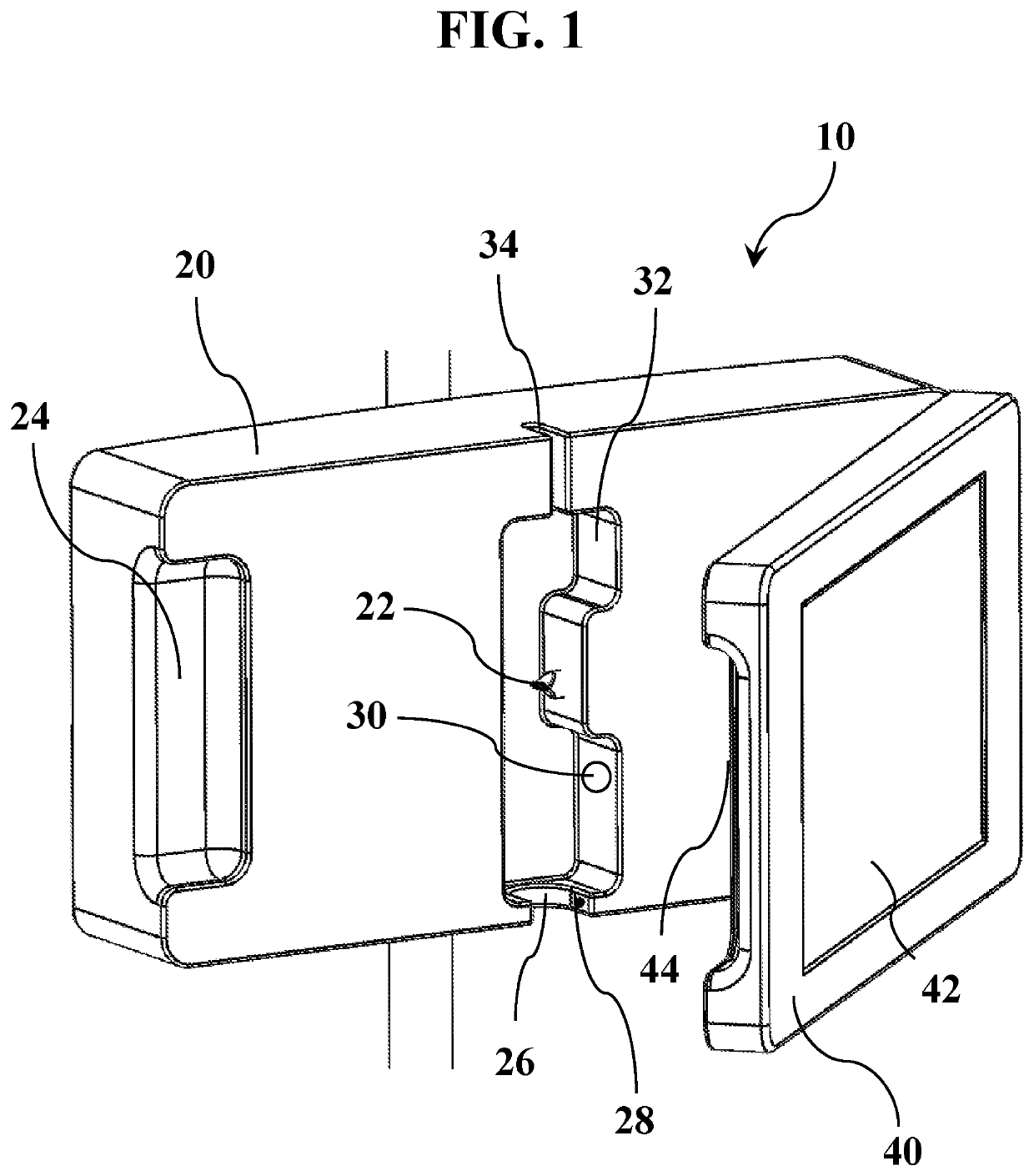
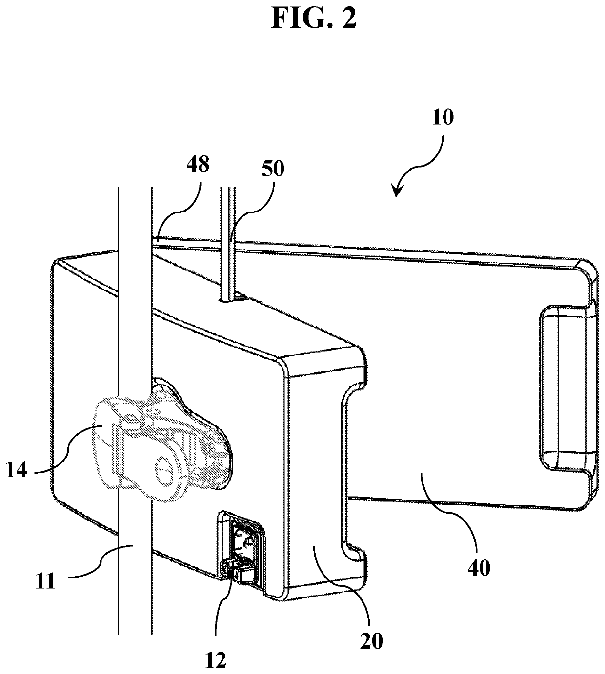
[0056]The present disclosure provides body fluid management systems that employ digital technologies to permit real-time monitoring and control of body fluid pressures or drainage flowrates while allowing or accounting for patient movement. Within certain embodiments, portable systems according to the present disclosure comprise, in operable combination, (1) a control system assembly and (2) a patient interface assembly. The body fluid management systems disclosed herein exhibit unexpected and surprising advantages over devices and technologies that are currently available in the art for monitoring and managing in vivo fluid pressures and flowrates.

[0057]This disclosure will be better understood in view of the following definitions, which are provided for clarification and are not intended to limit the scope of the subject matter that is disclosed herein.

Definitions

[0058]Unless specifically defined otherwise herein, each term used in this disclosure has the same meaning as it would ...


PUM


Abstract

Provided are body fluid management systems for patient care that include, in operable combination, a control system assembly comprising a fluid flow detection and control subassembly, a user data interface, a patient interface assembly comprising a wearable pressure sensor subassembly having a pressure sensor in the path of said body fluid for attaching directly to a patient proximate to an anatomical marker and an orientation sensor to monitor and / or control the pressure and / or flowrate of a body fluid such as cerebrospinal fluid, blood, or urine.

Description

CROSS-REFERENCE TO RELATED APPLICATIONS[0001]This U.S. non-provisional patent application was filed on Sep. 3, 2021 as U.S. patent application Ser. No. 17 / 466,301 and claims the benefit of U.S. Provisional Patent Application No. 63 / 074,223, which was filed on Sep. 3, 2020. The contents of U.S. Provisional Patent Application No. 63 / 074,223 are incorporated herein by reference in their entirety.BACKGROUND OF THE DISCLOSURETechnical Field[0002]The present disclosure relates, generally, to the field of medicine, in particular to medical devices, and associated procedures, for monitoring and / or controlling body fluid pressure, drainage flowrate, and patient movement. Disclosed herein are body fluid management systems for human and animal use, which provide real-time and integrated control of body fluid pressure and body fluid drainage flowrate that accommodate for frequent changes in the orientation and / or movement of a non-stationary patient.Description of the Related Art[0003]The medic...

Claims


Application Information

Patent Timeline
Patent Type & Authority Patents(United States)
IPC IPC(8): A61M5/168A61M27/00A61M5/142A61M25/00A61M1/00A61M5/172
CPCA61M5/168A61M1/772A61M5/142A61M25/0017A61M27/00A61M27/006A61M2005/1726A61M2202/0464A61M2205/3334A61M2205/505A61M2209/088A61M2230/30A61M2230/62A61M2230/63A61M2202/0496A61M1/84A61M1/74A61B5/031A61B5/208A61B5/205A61M1/70A61M5/16831A61M2210/0693A61M2210/1085
Inventor MORSE, STEPHEN A.MORSE, CAITLIN D. C.
Owner BRAINSPACE INC
Learn More