
RF frontend interface for a 61 GHz radio powered communication tag device

a radio-powered communication and frontend interface technology, applied in the direction of slot antennas, record carriers used with machines, antenna supports/mountings, etc., can solve the problem that the nfc communication solution cannot be downsized to the level of an integrated circuit, the antenna matching circuit cannot provide high q circuit elements, and the integrated circuit design of low loss antenna matching circuits cannot achieve the effect of maximum performance and lowest cos

Active Publication Date: 2021-07-13
RACYICS
View PDF7 Cites 0 Cited by
  • Summary
  • Abstract
  • Description
  • Claims
  • Application Information

AI Technical Summary

Benefits of technology

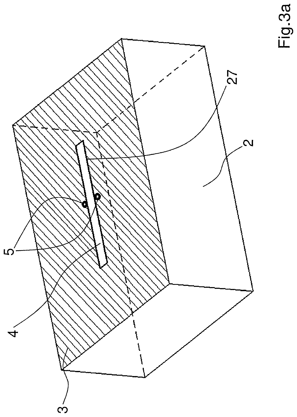
The patent describes a structure for a radio frequency frontend interface that uses a rectifier circuit for energy harvesting and communication. The rectifier circuit is placed between the antenna and the RF feed, which reduces lossy transmission lines and improves performance. The design also includes RF capacitors, DC capacitors, and rectifier transistors which are symmetrically placed to the antenna to stabilize its resonant frequency against varying materials. The structure is cost-effective and efficient for millimeter wave energy harvesting and communication systems.

Problems solved by technology

Due to the resistance in narrow gauge on chip metal and conductive bulk material the standard silicon technologies do not provide high Q circuit elements.
Therefore, it is impossible to implement low loss antenna matching circuits for larger impedance differences in an integrated circuit (IC) design.
Current UHF RFID and NFC communication solutions cannot be down sized to the level of an integrated circuit.
Depending on the RFID variant, there are strong mounting limitations on conductive and ferromagnetic materials like steel and other metals.

Method used


Image

  • RF frontend interface for a 61 GHz radio powered communication tag device
  • RF frontend interface for a 61 GHz radio powered communication tag device
  • RF frontend interface for a 61 GHz radio powered communication tag device

Examples


Embodiment Construction

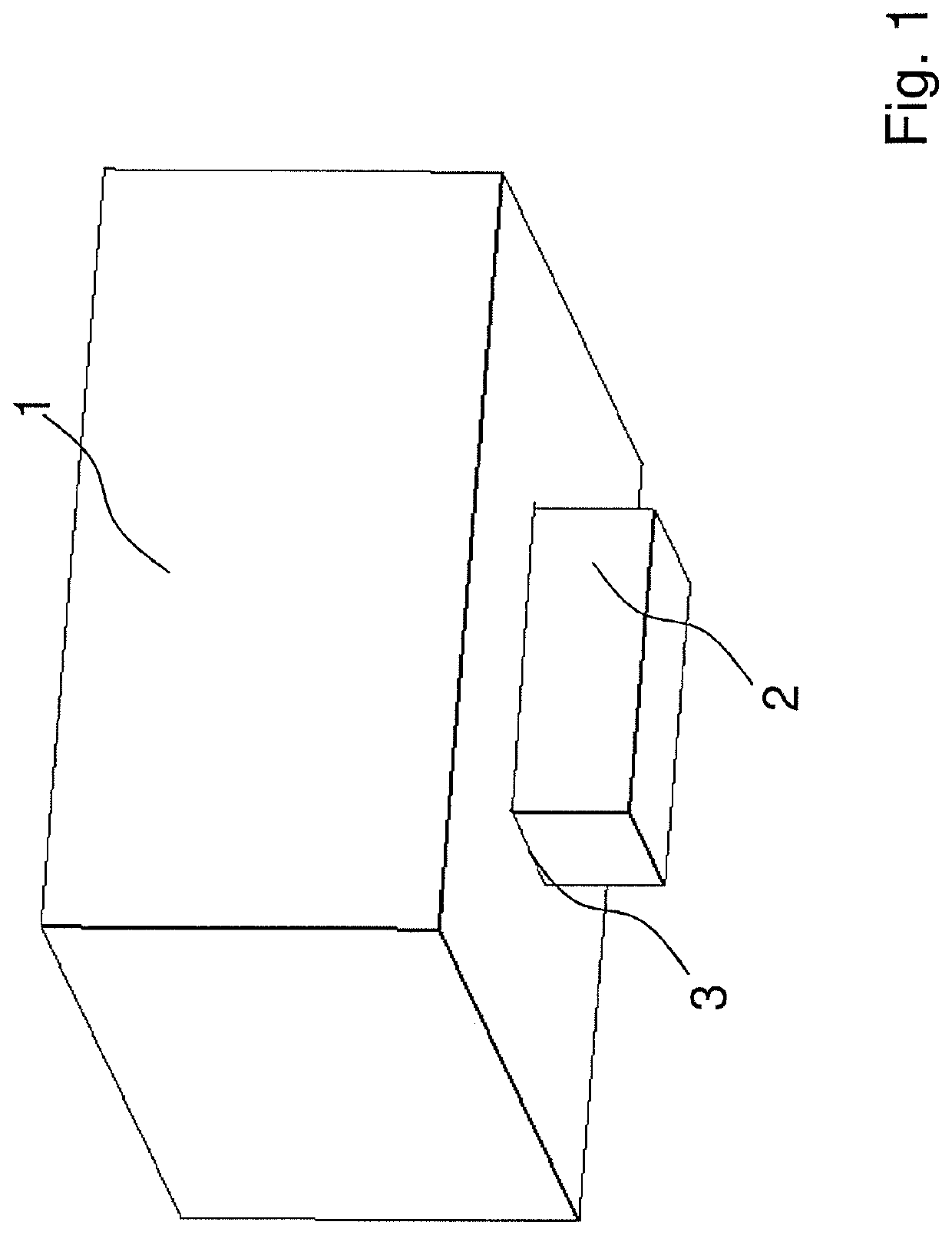
[0047]In a preferred embodiment of the inventive RF frontend interface for a 61 GHz radio powered communication tag device the resonant body 1 or dielectric resonator as shown schematically in FIG. 1 is mounted on top of a silicon die 2 to support the antenna performance against the conductive bulk material and to serve as a mechanical carrier. The dielectric resonator material has been chosen with a dielectric constant of 5 or higher. Since most of the plastic material in daily life have dielectric constants smaller than 4, the bodies resonance and radiation properties are barely affected when the tag is mounted in most of the daily life materials. At the same time, only the dielectric resonator 1 must meet the size requirements for free space radiation and can be made of much cheaper material than the integrated circuit. This will allow further reducing the required silicon die 2 size and therefore the costs.

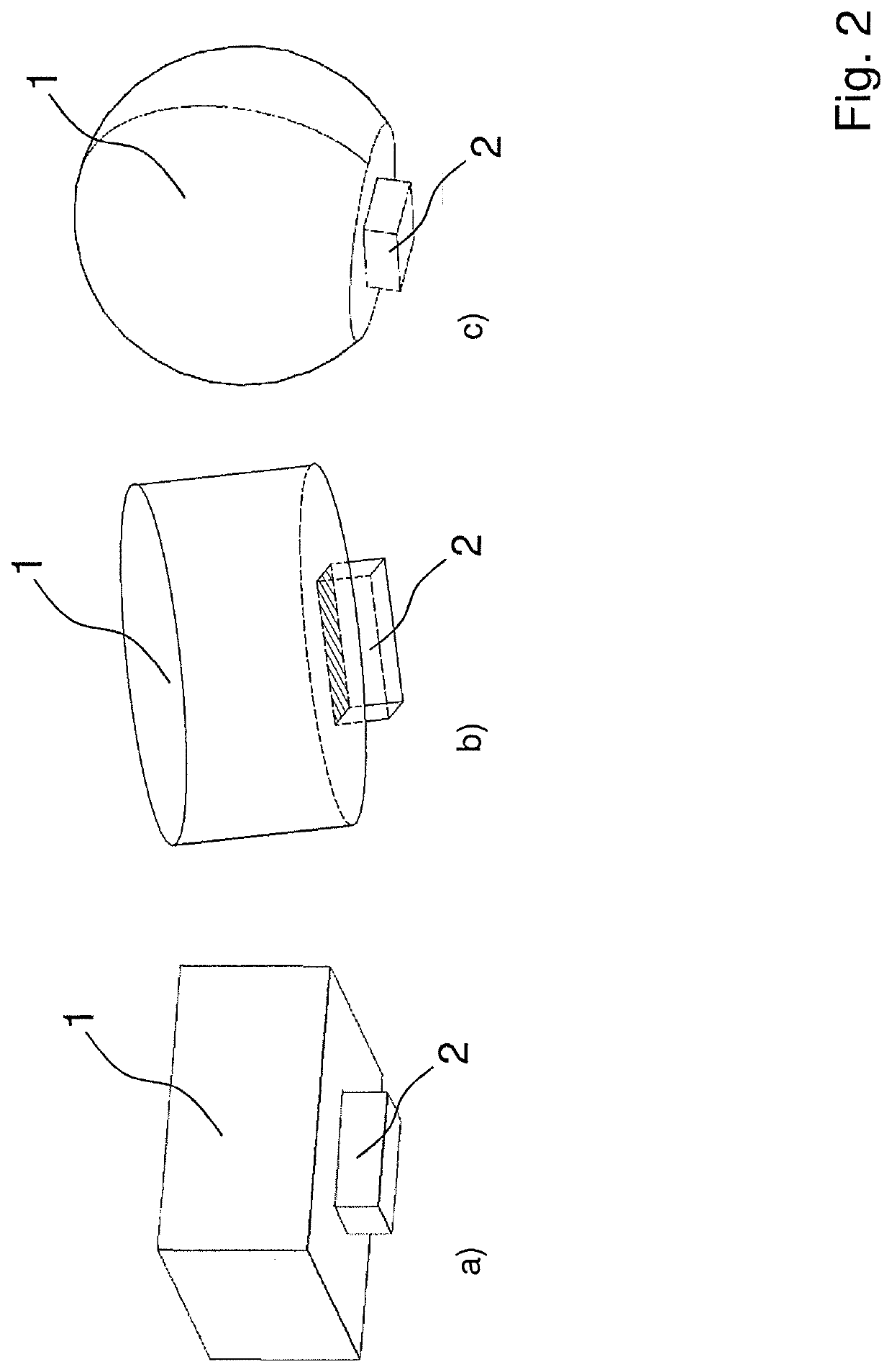
[0048]FIG. 2 shows different resonator body 1 shape variants. As typical ...


PUM


Abstract

A RF frontend interface for a 61 GHz radio powered communication tag device with a built-in antenna includes an IC embedded in a silicon die with a top metallization layer and a dielectric resonant body linked to the silicon die. A high impedance antenna with two feed points is embedded into the top metallization layer and a RF rectifier and multiplier circuit connected to the antenna feed is integrated in the silicon die and symmetrically placed between the antenna feed points configured to stabilize the antenna resonant frequency with its inherent capacity against varying surrounding materials and generate a positive and negative DC output supply voltage against a bulk potential of the silicon die for directly operating a digital circuit in FDSOI technology embedded in the silicon die. The resonant body is configured to work as a wavelength translator in between the antenna and free space.

Description

CROSS REFERENCE TO RELATED APPLICATIONS[0001]This application is a U.S. Patent Application filing which claims priority to European Application No.: EP19157650.3, filed on Feb. 18, 2019, which is hereby incorporated by reference herein in its entirety.[0002]The invention relates to a radio frequency (RF) frontend interface for a 61 GHz radio powered communication tag device.BACKGROUND[0003]Advancing steps for existing RFID and NFC technologies are the reduction of size and costs as well as to overcome mounting limitations on conductive materials. On chip antenna integration is a logical step. For given integrated circuit die sizes this leads to millimeter wave frequencies with focus to the license free ISM (Industrial, Scientific and Medical) band at 61 GHz.[0004]The antenna integration on standard advanced node semiconductor technologies will face the following challenges: dealing with the resistive loss in typical low resistive integrated circuit (IC) bulk material; the need of sh...

Claims


Application Information

Patent Timeline
Patent Type & Authority Patents(United States)
IPC IPC(8): G06K19/02G06K19/077H01Q1/24H01Q13/18
CPCG06K19/07773G06K19/0772G06K19/07749H01Q1/248H01Q13/18H01Q1/2225H01Q1/2283H01Q9/0485H01Q13/10
Inventor KLOSA, THOMASHÖPPNER, SEBASTIAN
Owner RACYICS
Learn More