
Copper rotation-suspension smelting process and copper rotation-suspension smelting device

a smelting process and copper technology, applied in vertical furnaces, lighting and heating devices, furnaces, etc., can solve the problems of high smoke rate, low oxygen availability, malignant situations, etc., and achieve the effect of improving the smelting effect of copper sulfid

Active Publication Date: 2020-02-25
YANGGU XIANGGUANG COPPER
View PDF15 Cites 0 Cited by
  • Summary
  • Abstract
  • Description
  • Claims
  • Application Information

AI Technical Summary

Benefits of technology

The process improves oxygen availability, reduces residue copper content, decreases fume incidence, and increases sulfur dioxide content in flue gas, while accommodating fluctuating feed amounts and enhancing productivity.

Problems solved by technology

The main core process employed in the space suspension smelting is a direct current jet technique which utilizes a combined action of wind in central distribution and wind in a vertical process to achieve a gas-solid contact reaction; however, due to the influence of the direct current properties in the aforementioned process, there would be malignant situations such as low oxygen availability, high smoke rate, severe erosion corrosion on furnace liners, raw material pile accumulation of concentrates within the furnace without any reaction, etc., during the production.
In order to address the above problems, a swirl injection technique has further developed in recent years, in which gas is spirally flowed to achieve a contact reaction with material particles; however, the working effectiveness thereof is still not ideal, and it cannot meet the development trend of smelting techniques: a high feeding amount, high load, high oxygen concentration and high working rate (“Four High” for short).
Therefore, how to further improve the smelting effect on copper sulfide has become a problem that currently and urgently needs to be solved for those skilled in the art.

Method used


Image

  • Copper rotation-suspension smelting process and copper rotation-suspension smelting device
  • Copper rotation-suspension smelting process and copper rotation-suspension smelting device

Examples


Embodiment Construction

The present invention provides a copper rotation-suspension smelting device which is capable of further improving the smelting effect of copper sulfide.

In the following, the technical solutions in the embodiments of the present invention will be clearly and completely described in conjunction with the figures in the embodiments of the present invention, and obviously, the described embodiments are only a part of embodiments of the present invention rather than all the embodiments thereof. Based on the embodiments in the present invention, all of the other embodiments which are obtained by those skilled in the art without any creative work fall within the protection scope of the present invention.

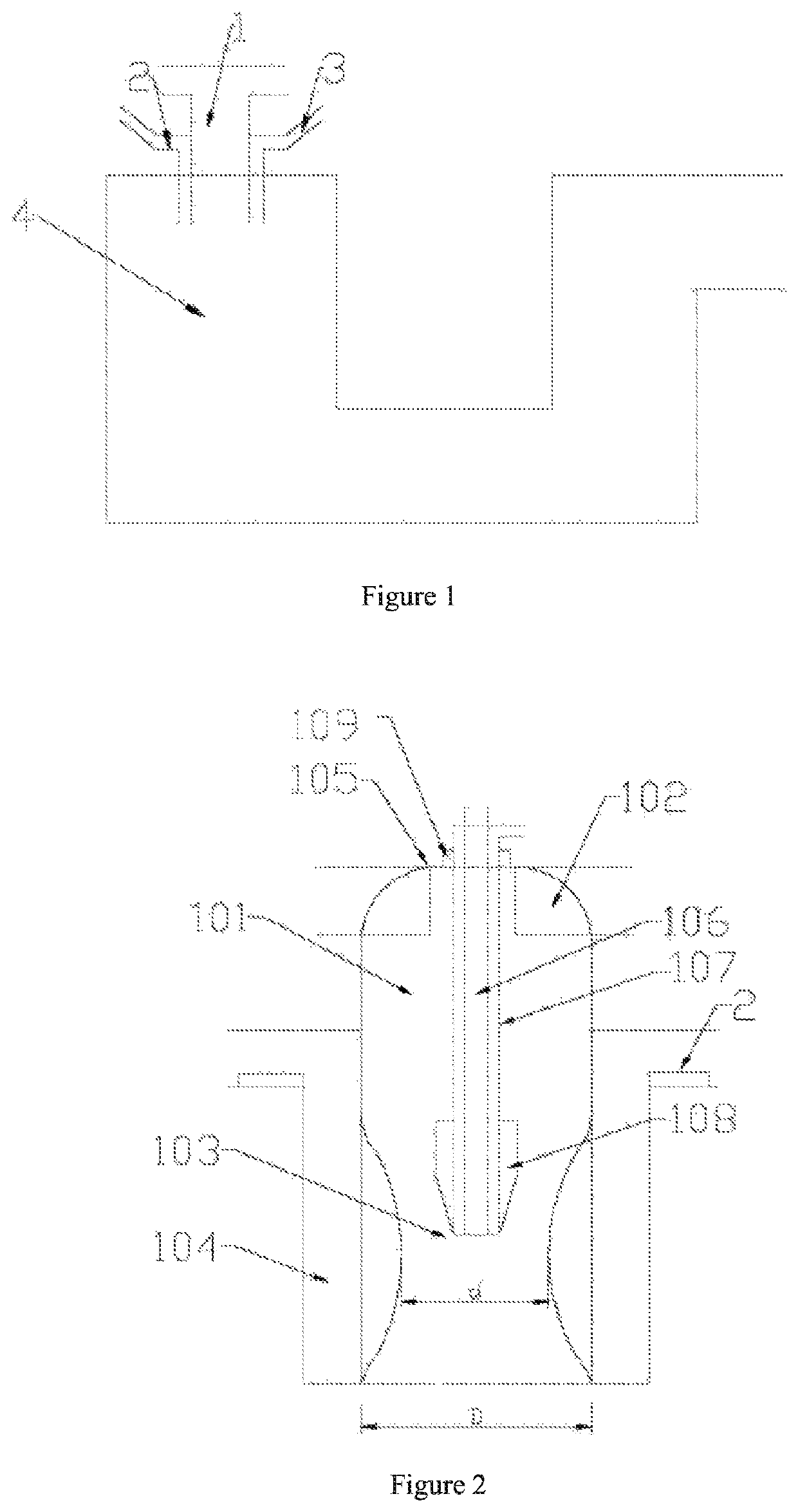
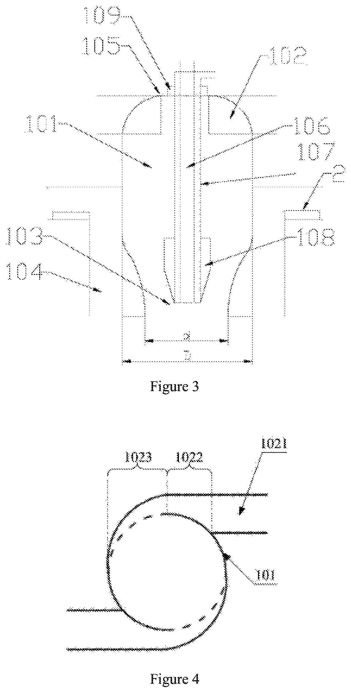
As shown in FIGS. 1-4, a copper rotation-suspension smelting device in an embodiment of the present invention mainly comprises a conveying pipe 3, a smelting furnace 4, and a nozzle 1 connecting the conveying pipe 3 in communication with the smelting furnace 4. The present application mainly...


PUM

PropertyMeasurementUnit
angle of inclinationaaaaaaaaaa
speedaaaaaaaaaa
movementaaaaaaaaaa

Abstract

Disclosed in the present application is a copper rotation-suspension smelting process comprising: mixing a flux and / or fume with dried copper-containing mineral powders to form a mixed material, which enters into a smelting furnace through a material channel; allowing a reaction gas to form a swirling flow under an action of a swirler, which enters into the smelting furnace through a Venturi channel under a guidance of a swirling gas channel; replenishing the reaction gas and / or a fuel to the smelting furnace through an auxiliary oxygen channel and an auxiliary fuel channel; subjecting the swirling flow which has been subjected to high-speed expansion through the Venturi channel and enters into the smelting furnace to a contact reaction with the mixed material; separating a melt generated by the reaction which falls into a settling tank into a residue layer and a copper-containing product layer.

Description

CROSS-REFERENCE TO RELATED APPLICATIONSThe present application claims the benefit of the priority to CN application No. 201610950066.6 titled “Copper rotation-suspension smelting process and copper rotation-suspension smelting device”, filed with the Chinese State Intellectual Property Office on Nov. 2, 2016, which is incorporated herein by reference in its entirety.FIELD OF THE INVENTIONThe present invention relates to the technical field of metal sulfide smelting, and in particular to a copper rotation-suspension smelting process as well as a copper rotation-suspension smelting device which is applicable to the copper rotation-suspension smelting process.BACKGROUND OF THE INVENTIONCurrently, a metal sulfide concentrate is generally smelted with a way of pyrometallurgy, that is, a process in which sulfur and iron in the metal sulfide concentrate are removed by reacting them with oxygen to finally obtain metals, in particular with respect to the pyrometallurgy on metals such as copp...

Claims


Application Information

Patent Timeline
Patent Type & Authority Patents(United States)
IPC IPC(8): C22B5/14F27B1/20F27B17/00
CPCF27B17/00F27B1/20C22B5/14C22B5/02C22B15/0047C22B15/0052C22B15/00
Inventor ZHOU, SONGLINGE, ZHELINGWANG, ZHIPU
Owner YANGGU XIANGGUANG COPPER
Learn More