
System and method for occluding contour detection

a contour detection and contour detection technology, applied in the field of system and method for occluding contour detection, can solve the problems of affecting the pixel-wise semantic segmentation unable to enable the identification of important objects in the input image, and the size of the feature map of the last few layers of the network is inevitably downsampled, so as to improve the pixel-wise semantic segmentation, improve the practical use effect, and effectively enlarge the network

Active Publication Date: 2018-09-04
TUSIMPLE INC
View PDF101 Cites 49 Cited by
  • Summary
  • Abstract
  • Description
  • Claims
  • Application Information

AI Technical Summary

Benefits of technology

The patent text describes a method for improving the accuracy of semantic segmentation in a deep learning system. The method involves using a combination of dense upsampling convolution and hybrid dilated convolution to capture more detailed information and alleviate issues with standard dilated convolution. Additionally, the method includes a contour-detection based approach for accurate object detection, which is useful for solving the problem of occluded object detection. The method can effectively detect object-level contours and improve the overall accuracy of semantic segmentation.

Problems solved by technology

Because of the operation of max-pooling or strided convolution in convolutional neural networks (CNNs), the size of feature maps of the last few layers of the network are inevitably downsampled.
However, these conventional systems can cause a “gridding issue” produced by the standard dilated convolution operation.
Other conventional systems lose information in the downsampling process and thus fail to enable identification of important objects in the input image.
Object contour detection is a fundamental problem for numerous vision tasks, including image segmentation, object detection, semantic instance segmentation, and occlusion reasoning.
Failure to detect an object (e.g., a car or a person) may lead to malfunction of the motion planning module of an autonomous driving car, thus resulting in a catastrophic accident.
Current object detection frameworks, although useful, cannot recover the shape of the object or deal with the occluded object detection problem.
This is mainly because of the limits of the bounding box merging process in the conventional framework.
In particular, problems occur when nearby bounding boxes that may belong to different objects get merged together to reduce a false positive rate, thus making the occluded object undetected, especially when the occluded region is large.
Bilinear upsampling is not learnable and may lose fine details.
For example, if a network has a downsample rate of 1 / 16, and an object has a length or width less than 16 pixels (such as a pole or a person far away), then it is more than likely that bilinear upsampling will not be able to recover this object.
Meanwhile, the corresponding training labels have to be downsampled to correspond with the output dimension, which will already cause information loss for fine details.
However, an inherent problem exists in the current dilated convolution framework, which we identify as “gridding”: as zeros are padded between two pixels in a convolutional kernel, the receptive field of this kernel only covers an area with checkerboard patterns—only locations with non-zero values are sampled, losing some neighboring information.
The problem gets worse when the rate of dilation increases, generally in higher layers when the receptive field is large: the convolutional kernel is too sparse to cover any local information, because the non-zero values are too far apart.
Information that contributes to a fixed pixel always comes from its predefined gridding pattern, thus losing a huge portion of information.
However, one problem exists in the above-described dilated convolution framework, the problem being denoted as “gridding.” As example of gridding is shown in FIG. 4.
As a result, pixel p can only view information in a checkerboard fashion, and thus loses a large portion (at least 75% when r=2) of information.
When r becomes large in higher layers due to additional downsampling operations, the sample from the input can be very sparse, which may not be good for learning because: 1) local information is completely missing; and 2) the information can be irrelevant across large distances.
Another outcome of the gridding effect is that pixels in nearby r×r regions at layer / receive information from a completely different set of “grids”, which may impair the consistency of local information.
However, single object-level or instance-wise object information is lost (e.g., all cars are rendered in the same color—blue, as representing the object category label for ‘cars’).
Failure to detect an instance of an object (e.g., a car or a person) may lead to a malfunction or mis-classification in the motion planning module of an autonomous driving car, thus resulting in a catastrophic accident.
These conventional object detection frameworks that use bounding boxes, although useful, cannot recover the shape of the detected object or deal with the occluded object detection problem (e.g., see FIG. 11).
In particular, due to the limitations of the bounding box merging process in the conventional object detection framework that uses bounding boxes, nearby bounding boxes that may belong to different objects or different object instances may be merged together to reduce a false positive rate.
As a result, occluded objects or occluded object instances may remain undetected, especially when the occluded region is large.
Thus, as shown in FIG. 11, conventional object detection using rectangular bounding boxes cannot recover the shape or contour of different objects or different object instances in the input image.
As a result, occluded objects or occluded object instances can be missed from detection due to the merging process of merging a bounding box of an object with the bounding box of the object's neighbor.
DUC can decode contours of arbitrary width, while other methods (such as bilinear upsampling) decode contours of a width of at least eight pixels wide, which is not acceptable in the present application.
For network training, however, one important issue is the dataset unbalancing problem: the number of pixels that are labeled as “object contour” is less than 1 percent of the number of pixels that are labeled as “non-contour” (or background).

Method used


Image

  • System and method for occluding contour detection
  • System and method for occluding contour detection
  • System and method for occluding contour detection

Examples


Embodiment Construction

[0022]In the following description, for purposes of explanation, numerous specific details are set forth in order to provide a thorough understanding of the various embodiments. It will be evident, however, to one of ordinary skill in the art that the various embodiments may be practiced without these specific details.

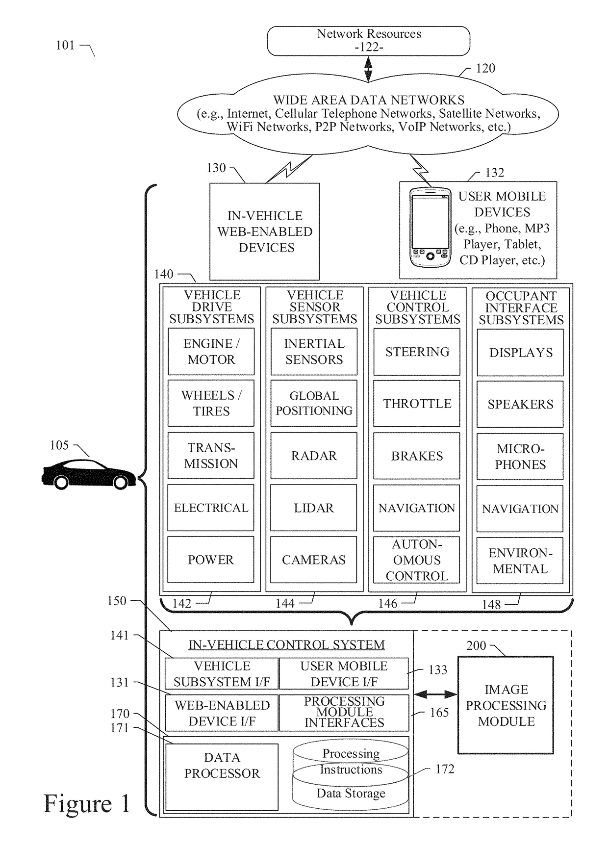
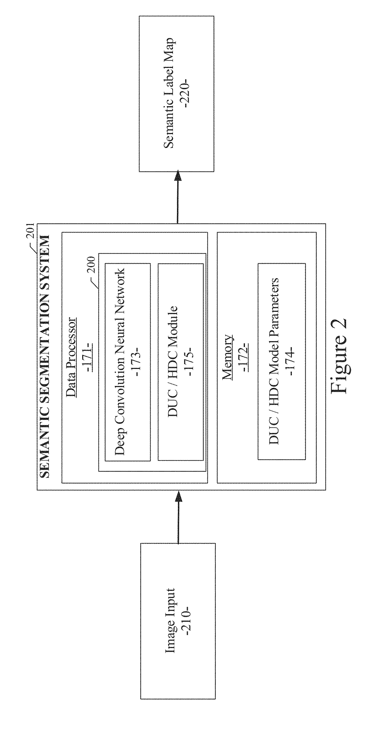
[0023]As described in various example embodiments, a system and method for occluding contour detection are described herein. An example embodiment disclosed herein can be used in the context of an in-vehicle control system 150 in a vehicle ecosystem 101. In one example embodiment, an in-vehicle control system 150 with an image processing module 200 resident in a vehicle 105 can be configured like the architecture and ecosystem 101 illustrated in FIG. 1. However, it will be apparent to those of ordinary skill in the art that the image processing module 200 described and claimed herein can be implemented, configured, and used in a variety of other applications and system...


PUM


Abstract

A system method for occluding contour detection using a fully convolutional neural network is disclosed. A particular embodiment includes: receiving an input image; producing a feature map from the input image by semantic segmentation; applying a Dense Upsampling Convolution (DUC) operation on the feature map to produce contour information of objects and object instances detected in the input image; and applying the contour information onto the input image.

Description

PRIORITY PATENT APPLICATION[0001]This is a continuation-in-part (CIP) patent application drawing priority from U.S. non-provisional patent application Ser. No. 15 / 456,219; filed Mar. 10, 2017. This present non-provisional CIP patent application draws priority from the referenced patent application. The entire disclosure of the referenced patent application is considered part of the disclosure of the present application and is hereby incorporated by reference herein in its entirety.COPYRIGHT NOTICE[0002]A portion of the disclosure of this patent document contains material that is subject to copyright protection. The copyright owner has no objection to the facsimile reproduction by anyone of the patent document or the patent disclosure, as it appears in the U.S. Patent and Trademark Office patent files or records, but otherwise reserves all copyright rights whatsoever. The following notice applies to the disclosure herein and to the drawings that form a part of this document: Copyrigh...

Claims


Application Information

Patent Timeline
IPC IPC(8): G05D1/02G06N3/04G06T7/11G06K9/46G06T7/70G06K9/66G06N3/08G05D1/00
CPCG05D1/0231G06K9/4628G06T7/70G06K9/66G06T7/11G05D1/0088G06N3/04G06N3/08G05D2201/0212G06V20/58G06V10/454G06V10/82G06V30/19173G06N7/01G06N3/045G06F18/24133
Inventor WANG, PANQUCHEN, PENGFEIHUANG, ZEHUA
Owner TUSIMPLE INC
Learn More