Eureka AIR delivers breakthrough ideas for toughest innovation challenges, trusted by R&D personnel around the world.

Manufacturing method of color filter

The technology of a color filter and manufacturing method, which is applied in the field of color filters, can solve problems such as complicated procedures, low material use efficiency, and high cost of liquid crystal displays, and achieve the effects of preventing color mixing and suppressing loss

Inactive Publication Date: 2006-08-30
DAINIPPON SCREEN MTG CO LTD
View PDF1 Cites 5 Cited by
  • Summary
  • Abstract
  • Description
  • Claims
  • Application Information

AI Technical Summary

Problems solved by technology

[0003] In the method of manufacturing a color filter by the dyeing method or the pigment dispersion method, in the process of applying a photosensitive dyed base material or photosensitive resist on a transparent substrate by spin coating, etc., it is inevitable that materials In addition, each time a coloring pattern of various colors such as red, green, and blue is formed, it is necessary to repeat the development process and the cleaning process
In this way, the efficiency of material use is low, and the process is complicated, so it becomes a main reason for the high cost of liquid crystal displays.
At the same time, the printing method has the problem that it is difficult to form a high-precision coloring pattern

Method used


Image

  • Manufacturing method of color filter
  • Manufacturing method of color filter
  • Manufacturing method of color filter

Examples


Embodiment Construction

[0023] Hereinafter, preferred embodiments of the present invention will be described with reference to the drawings.

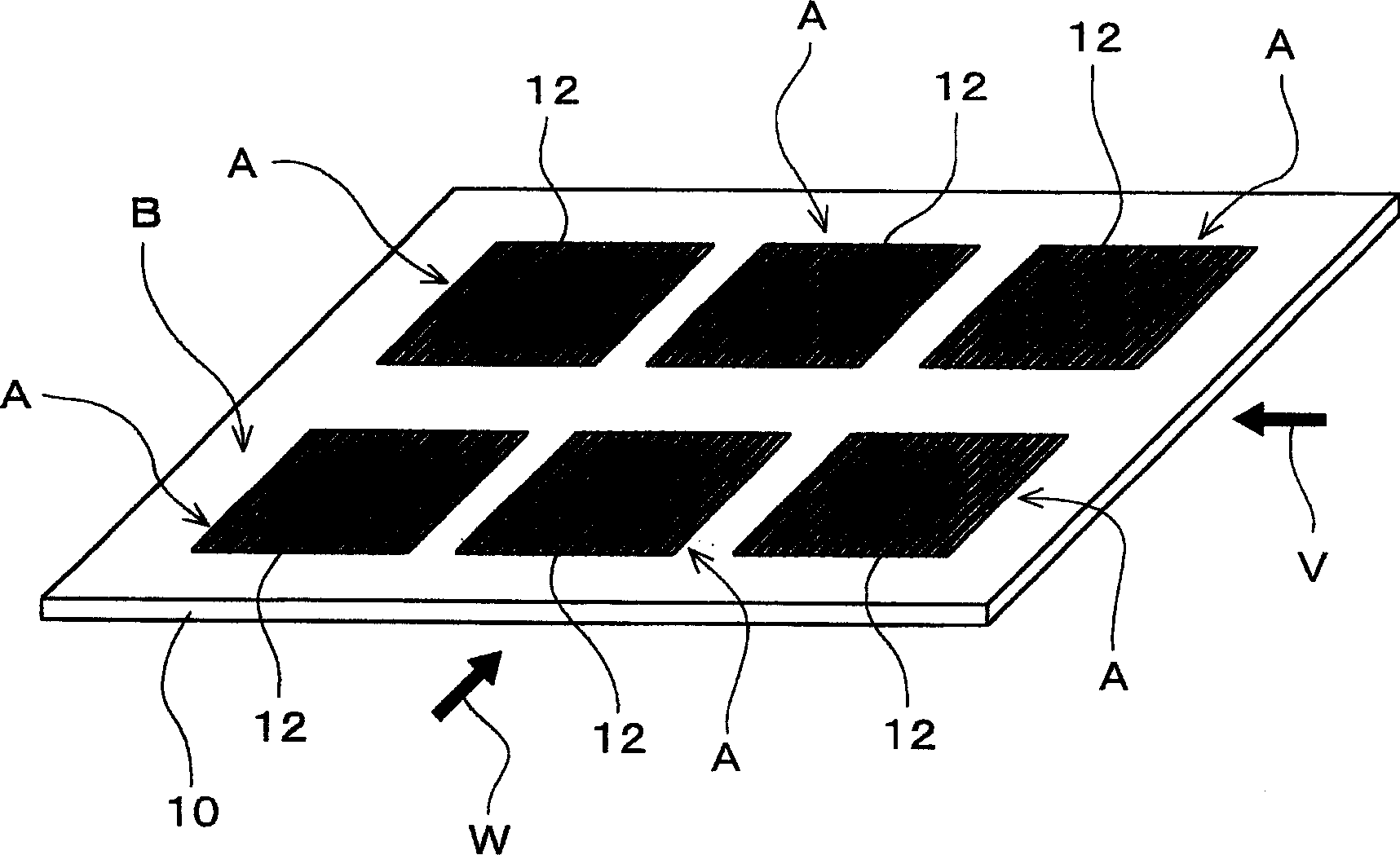
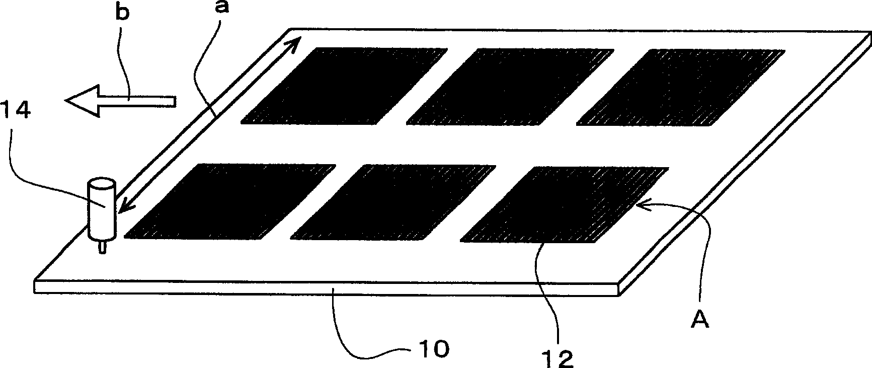
[0024] Figure 1 to Figure 10 It shows an example of embodiment of this invention, and is a figure for demonstrating each process in the manufacturing method of a color filter.

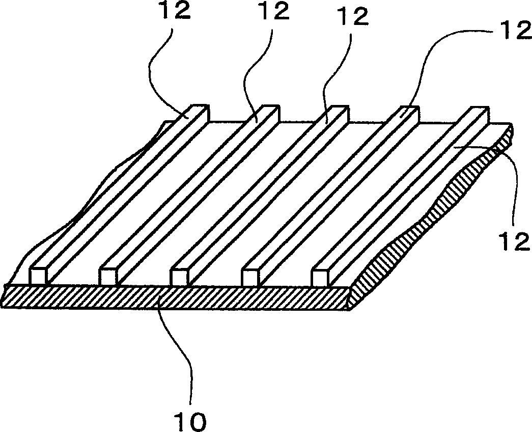
[0025] Before manufacturing a color filter, first, light-shielding banks (banks) of a predetermined pattern are formed on a transparent substrate, for example, a transparent glass substrate. figure 1 It is a schematic perspective view showing the state in which a boss is formed on a glass substrate. figure 2 It is a partial perspective view in which a part is enlarged. figure 1 An example in which six parts are taken is shown, and six effective regions A corresponding to the effective parts of the color filter are provided on one glass substrate 10 .

[0026] The boss 12 is a member that functions as a super black matrix in a color filter, and is made of a light-shielding material...


PUM


Abstract

Provided is a manufacturing method of color filter capable of improving the availability factor of material, simplifying processes and forming high-definition colored pattern. The manufacturing method of color filter comprises a process of applying coloring material between banks 12 on a glass substrate by delivering the coloring material from a nozzle 14 while scanning the nozzle for the glass substrate 10 on which the light-shielding banks 12 of a prescribed pattern are formed and intermittently feeding the glass substrate with a prescribed pitch in the direction orthogonal to the scanning direction, a process of aligning and laminating a mask plate on which a light transmission part corresponding to an available part of the color filter is formed, on the back surface side of the glass substrate, exposing light from the back surface side of the glass substrate via the mask plate and curing the color material applied on the part corresponding to the available part of the color filter and a process of developing the surface side of the glass substrate and dissolving and removing the coloring material which is applied on the part corresponding to non-available part of the color filter and is left uncured.

Description

technical field [0001] The present invention relates to a method of manufacturing a color filter used in a color liquid crystal display, an organic EL (electroluminescence) display device, an FED (field emission display: field emission display) device, or the like. Background technique [0002] For example, the color filters of color liquid crystal displays have been manufactured using the following method, that is, the dyeing method, which is used to apply a photosensitive dyed substrate to a transparent substrate, and the dyed substrate is dyed through a photomask. The base material is exposed and developed, and the dyed base material formed into a predetermined pattern is dyed as a colored layer; the pigment dispersion method is used to apply a photosensitive resist dispersed with a colored pigment on a transparent substrate, and through light A mask is used to expose and develop a photosensitive resist to form a colored layer of a predetermined pattern; a printing method...

Claims


Application Information

Patent Timeline
Patent Type & Authority Applications(China)
IPC IPC(8): G02B5/23B41J2/01G03F7/00G02F1/1335
CPCG02F1/133516G02F1/133512G02B5/223G02F1/1335
Inventor 西洼宏昭尾本贡一藤本好博
Owner DAINIPPON SCREEN MTG CO LTD
Why Eureka
Eureka Blog
Learn More