Plasma treatment apparatus and method

A plasma and equipment technology, applied in the field of fiber materials, which can solve problems such as economical infeasibility

Inactive Publication Date: 2006-06-07
COMMONWEALTH SCI & IND RES ORG +1
View PDF3 Cites 6 Cited by
  • Summary
  • Abstract
  • Description
  • Claims
  • Application Information

AI Technical Summary

Problems solved by technology

Both superatmospheric and subatmospheric plasma treatments and plasma treatments involving noble gases are not economically viable due to their cost

Method used


Image

  • Plasma treatment apparatus and method
  • Plasma treatment apparatus and method

Examples


Embodiment Construction

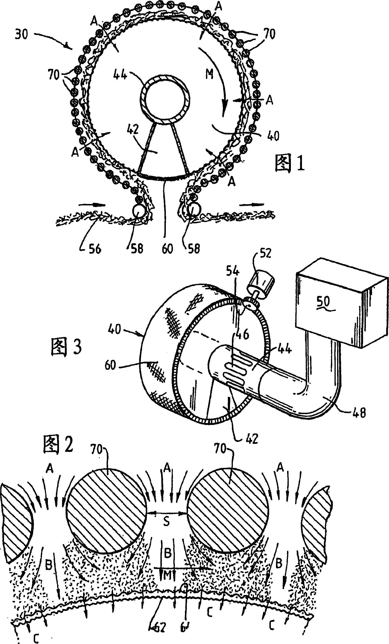
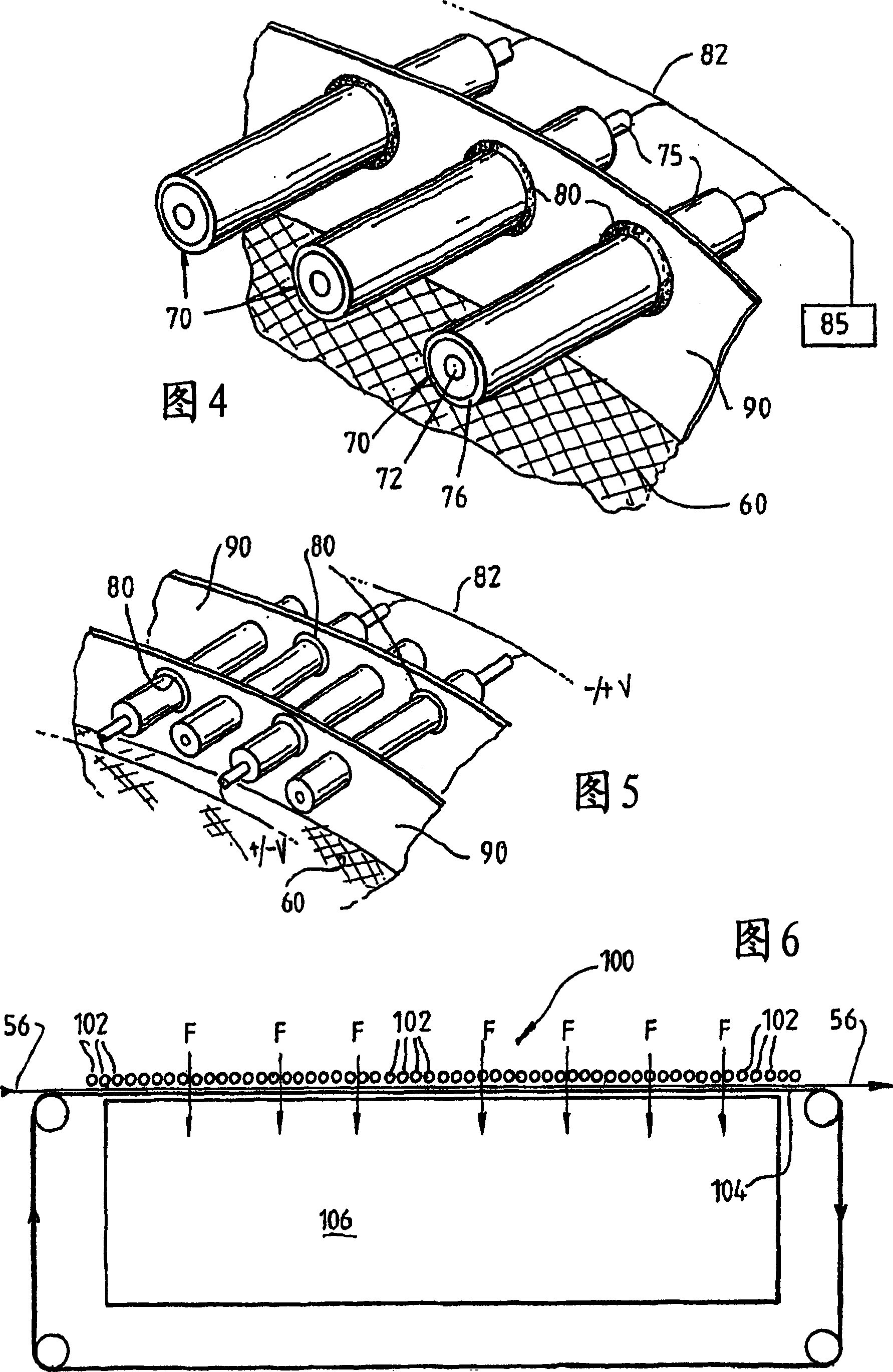
[0055] Referring first to Figures 1 and 2, it can be seen that the plasma processing apparatus 30 includes a hollow, rotatable drum 40 having a first electrode formed on the curved outer surface of the drum 40 in the form of a mesh electrode 60 thereon. The device 30 further includes a second electrode formed as a plurality of rod electrodes 70 spaced radially outward from the mesh electrode 60 .

[0056] The mesh electrode 60 includes a coarse mesh 62 that supports an overlying fine mesh 64 . The fine mesh 64 prevents the localization of the plasma microdischarge by providing a large array of potential plasma formation sites, where a reduced number of potential plasma formation locations will generally result in plasma microdischarge compared to the coarse mesh 62. Electrical localization.

[0057] As shown in FIGS. 1 and 3 , the drum 40 has a tubular core 44 and wedge-shaped baffles 42 extending from the core to the periphery of the drum 40 . The core 44 extends through th...


PUM


Abstract

Plasma-treated gas-permeable material produced by applying an alternating voltage between spaced apart electrodes, at least one of which is coated with a dielectric barrier layer, at least one of which consists of a plurality of separate electrode segments , thereby generating plasma microelectrodes between the separated electrodes. A gas permeable material is passed between or adjacent to the spaced electrodes. Gas moves between the electrode segments into and through the spaces between the electrodes and through the gas permeable material. The gas flows across the plasma-generating surfaces of the corresponding electrode segments at a rate such that the gas flow between the electrodes thus separated is in a turbulent state and causes the plasma micro-emissions to randomize and disperse the plasma products, These products would otherwise cause combustion instabilities in the gas permeable material, so that the randomized plasma microdischarge can provide an overall uniform plasma treatment of the gas permeable material. At the same time, the equipment used for the design process is also disclosed.

Description

technical field [0001] The present invention relates to a method and apparatus for plasma treatment of gas-permeable materials, such as fibrous materials. The present invention is particularly useful when used to treat wool. Background technique [0002] Plasma is widely used in material processing to change the surface properties of materials. Typically, this treatment is useful where the material surface is evenly distributed. When used on wool fibers, plasma treatment is used to oxidize the lipid layer on the fiber surface. Oxidation of the lipid layer can make wool fibers more receptive to subsequent surface treatments, such as anti-shrinkage treatments and anti-pilling treatments. [0003] Removing the lipid layer can also increase friction between fibers. This will be more beneficial to the spinning process, as spinning requires as few windings as possible. A lower level of winding increases the output efficiency of the spinning yarn and thus enables the downstrea...

Claims


Application Information

Patent Timeline
IPC IPC(8): D06M10/02B01J19/08H05H1/00
Inventor 尼尔·芬恩拉迪斯拉弗·柯维兹朱尔格·舒茨安东尼·法默尔
Owner COMMONWEALTH SCI & IND RES ORG
Why Eureka
Try Eureka