
Semi submersible type under water construction flow blocking device

A kind of underwater construction and semi-submersible technology, which is applied in the direction of underwater operation equipment, transportation and packaging, erection/assembly of bridges, etc. It can solve the problems that cannot be used to maintain underwater buildings, long construction period, rapid water flow, etc.

Inactive Publication Date: 2005-03-02
SHANGHAI JIAO TONG UNIV
View PDF0 Cites 6 Cited by
  • Summary
  • Abstract
  • Description
  • Claims
  • Application Information

AI Technical Summary

Problems solved by technology

...The disadvantages of the caisson foundation are: the construction period is long; when fine sand and silt soil are pumped in the well, quicksand phenomenon is easy to occur, causing the caisson to tilt; Excessive inclination of the bottom rock surface will bring certain difficulties to the construction
"In addition to the "long construction period" described in the article; the phenomenon of quicksand is easy to occur when pumping water in the well for fine sand and silt soil, causing the caisson to tilt; Excessive inclination will bring certain difficulties to the construction” and other disadvantages, the caisson has a small application range and can only play a role in retaining water when it is built as a foundation and cannot be used to maintain completed underwater buildings (some The piers of some offshore bridges are supported by steel pipe piles, and sacrificial anodes (anti-corrosion zinc blocks) need to be laid for protection. The laying of anti-corrosion zinc blocks is welded to the steel pipe piles by divers underwater
Due to the turbid water quality and rapid current in the sea area where some offshore bridges are located, divers can work underwater for a short time, and it is difficult to ensure the welding progress of steel pile anti-corrosion zinc blocks), one-time use cannot be reused

Method used


Image

  • Semi submersible type under water construction flow blocking device
  • Semi submersible type under water construction flow blocking device
  • Semi submersible type under water construction flow blocking device

Examples


Embodiment Construction

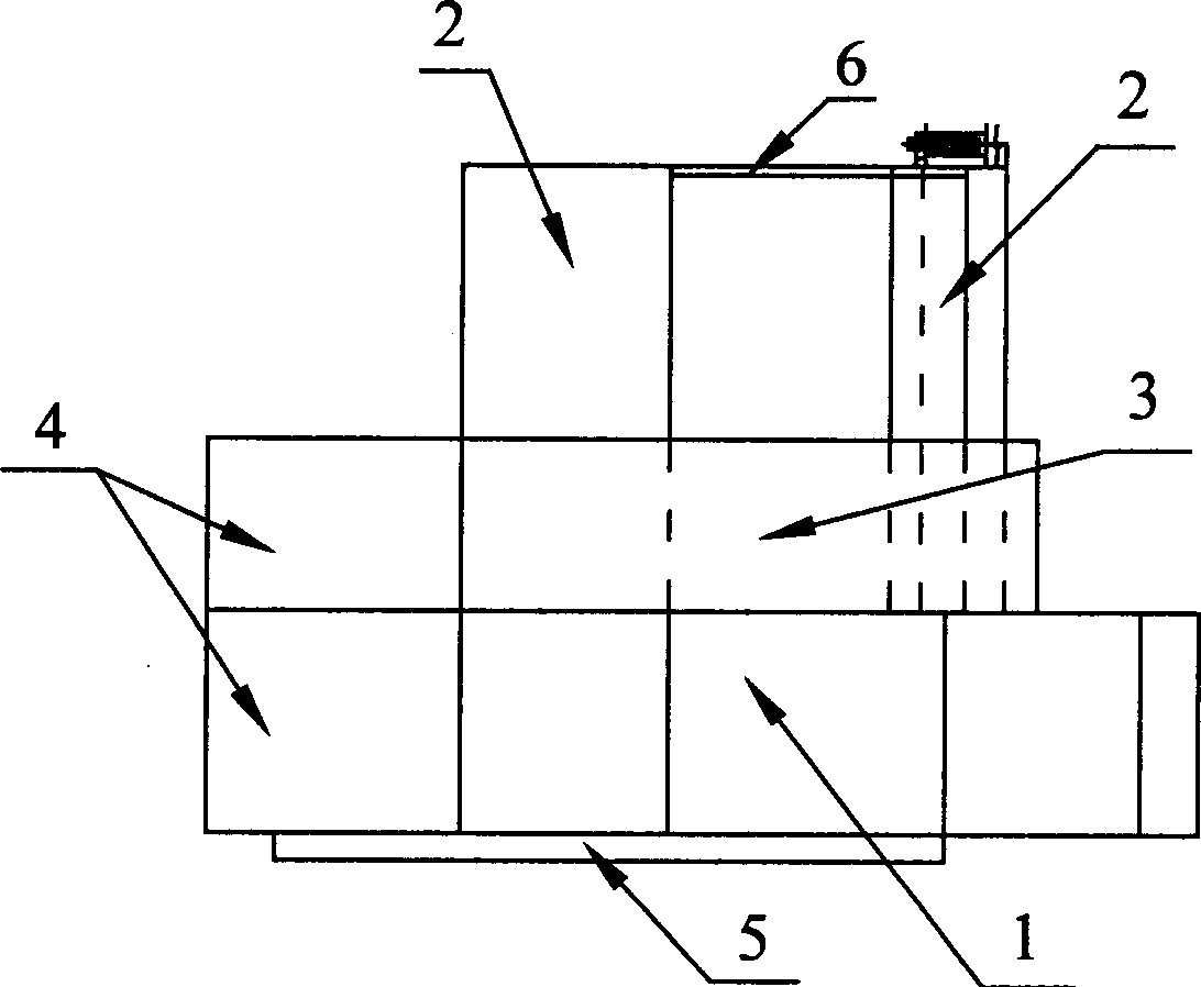
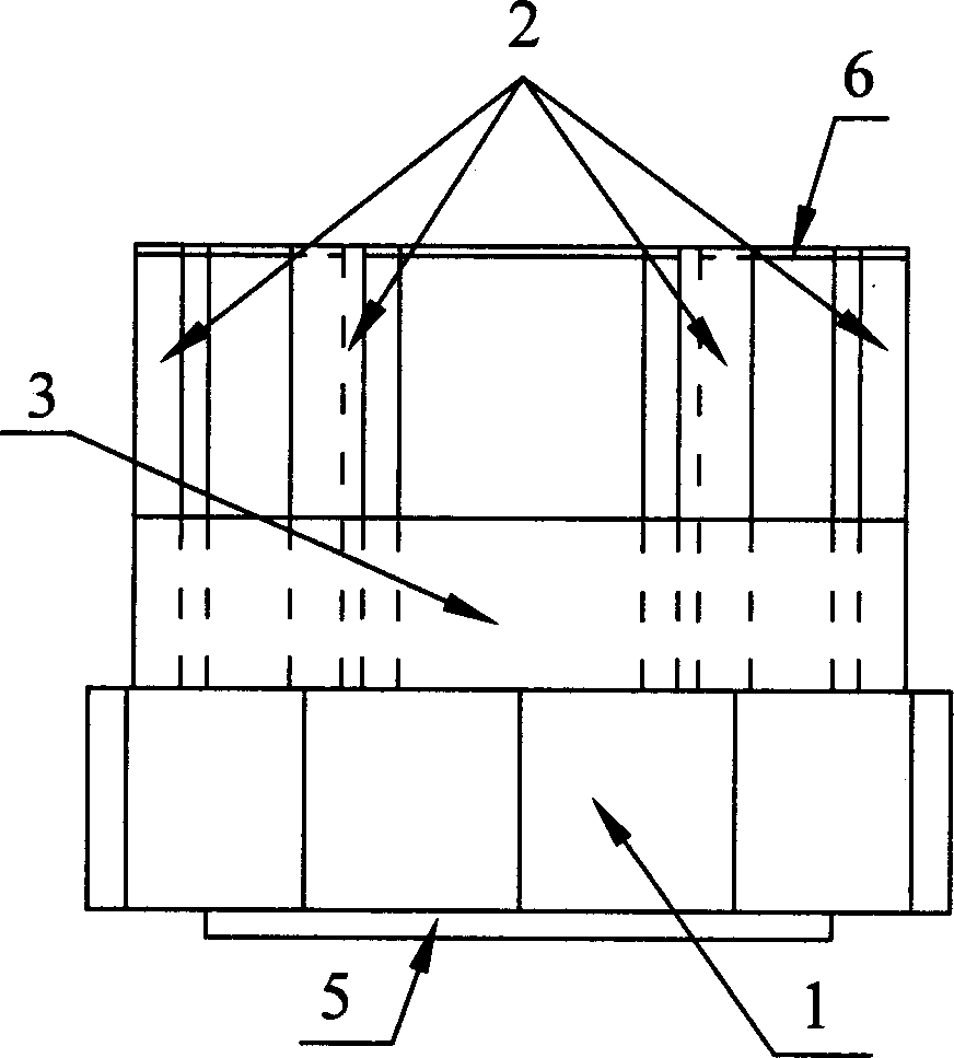
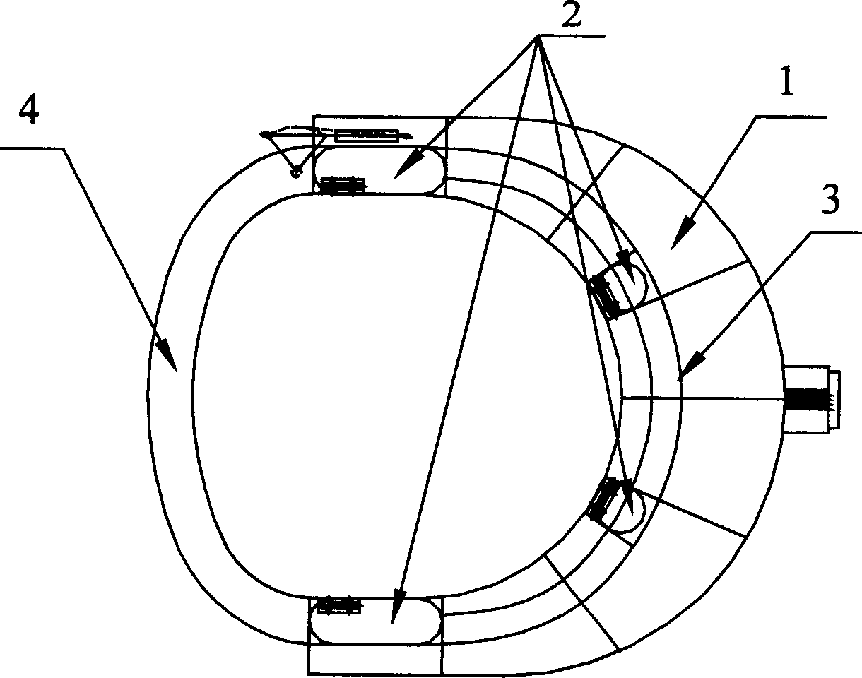
[0017] Such as Figure 1-3 As shown, the present invention includes: a hull 1, a column 2, a baffle plate 3, a door 4 that can be opened and closed, and a deck 6. The connection relationship is: the bow of the hull 1 has an opening, and the entire ship is U-shaped. Each of the four corners of the opening is provided with a column 2, which is set in the baffle 3, and the baffle 3 is connected between the columns 2. The head of the entire device is provided with a door 4 that can be opened and closed. The column 2 on the left of the bow of the hull 1 is connected. When the door 4 is closed, it is connected with the column 2 on the right of the bow of the hull 1. The deck 6 is laid on the upper part of the entire device and is supported by the four columns 2.

[0018] An apron 5 is also provided at the lower end of the hull 1 and the door 4. The part of the upright 2 higher than the baffle 3 is transformed into a cylinder or has rounded corners. Door 4 adopts an arched door.

[0019]...


PUM


Abstract

The present invention relates to water flow blocking apparatus for semi-submersed underwater construction, and belongs to the field of marine engineering technology. The water flow blocking apparatus has a U-shaped hull with opening in the prow; four upright columns in the four corners of the opening; flow blocking plates connecting the upright columns; door hinged to the upright columns in the prow; and decks laid in the upper part of the apparatus and supported with the four upright columns. The present invention may be used to surround a steel pipe pile group of pier to form one job area with less water flow influence, and this can ensure the job stability in floating and semi-submersed operation. In addition, the present invention may be also applied in other places where less water flow influence on operation is needed.

Description

Technical field [0001] The invention relates to an underwater device used in the technical field of marine engineering, in particular to a semi-submersible underwater construction flow blocking device. Background technique [0002] The underwater construction baffle is a kind of water-retaining cofferdam structure. In the case of turbid water quality and rapid water flow in the construction water area, which is not conducive to the operation, the device can block the external water flow to form a work area with little water flow impact. [0003] Discovered prior art document retrieval, "Introduction to Civil Engineering" (Author: Jiang see whales, Ip Chi Ming editor, Press: Higher Education Press, Publication Date: July 2001 first edition) a book of 45,46,108 , 109, 202, and 203 mentioned a device called a "caisson". Its self-description reads: "A caisson is a well-shaped structure. It is used to excavate soil in the well and rely on its own weight to overcome the friction of the...

Claims


Application Information

Patent Timeline
IPC IPC(8): B63B38/00B63C11/00E01D22/00
Inventor 丁金鸿谭家华何炎平
Owner SHANGHAI JIAO TONG UNIV
Learn More