
Micro-liquid extracting method and apparatus on micro-analytic chip

A micro-analysis and extraction technology, which is applied in separation methods, analysis materials, solvent extraction, etc., can solve the problems of low concentration ratio and no application of microfluidic chips, and achieve simple channel configuration, easy operation, and chip structure simple effect

Inactive Publication Date: 2005-02-16
ZHEJIANG UNIV
View PDF0 Cites 4 Cited by
  • Summary
  • Abstract
  • Description
  • Claims
  • Application Information

AI Technical Summary

Problems solved by technology

The feature of this type of method is that the operation is relatively simple, but because it is based on the continuous flow of the organic phase and the aqueous phase, the ratio of the two phases is not easy to exceed 10 (aqueous phase / organic phase), so the concentration ratio of the extraction is not high. , it is difficult to exceed 100 times
[0005] In the conventional liquid-liquid extraction system, the operation mode of stop-flow extraction can obtain hundreds of times of extraction concentration ratio, and the mode of liquid droplet extraction can reach thousands of times of concentration (W.Liu and H.K.Lee, Anal .Chem, 72, 4462-4467 (2000)) (H.Liu and P.K.Dasgupta, Anal.Chem., 68, 1817-1821 (1996)) but the above two modes are not applied to the field of microfluidic chip analysis

Method used


Image

  • Micro-liquid extracting method and apparatus on micro-analytic chip
  • Micro-liquid extracting method and apparatus on micro-analytic chip
  • Micro-liquid extracting method and apparatus on micro-analytic chip

Examples


Embodiment 1

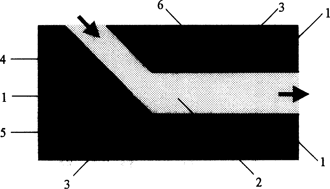
[0032] Reference figure 1 . Is a top view of a preferred embodiment 1 according to the present invention. The chip 1 channel configuration is a Y-shaped structure. The flowing liquid phase 2, the channel 4 and the fixed liquid phase 3, and the channel 5 present a cross-converging channel configuration, and a microstructure 6 that traps the fixed liquid phase 3 is processed on the flowing liquid phase channel 4 and the side walls. The fixed liquid phase 3 flow is introduced by the fixed liquid phase channel 5, and the mobile liquid phase 2 is introduced by the mobile liquid phase channel 4. During extraction, a certain volume of the fixed liquid phase 3 is trapped in the microstructure 6, or the flow of the fixed liquid phase 3 is stopped, and a fixed liquid phase 3 and a mobile liquid phase 2 are formed at the outlet of the fixed liquid phase channel 5. Interface; mobile liquid phase 2 maintains a flowing state, and the thick arrow indicates the flow direction of the mobile liqui...

Embodiment 2

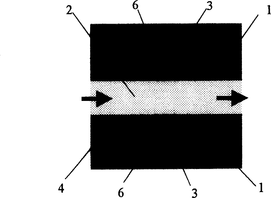
[0039] Refer to figure 2 Among them, two different configurations of concave microstructures 6 for trapping the fixed liquid phase 3 are processed on the sidewalls of the flowing liquid phase 2 channel 4 of the chip 1, and the sidewall microstructures 6 on the channel in the figure are rectangular structures; The sidewall microstructure 6 under the channel is a narrowed structure, which is beneficial to form a stable and reproducible interface between phases. When the extraction is in progress, a certain volume of the fixed liquid phase 3 is trapped in the microstructure 6, and the mobile liquid phase 2 remains in a flowing state, and the thick arrow indicates the flow direction of the mobile liquid phase.

Embodiment 3

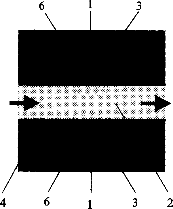
[0041] Refer to image 3 Among them, two other concave microstructures 6 with different configurations for trapping the fixed liquid phase 3 are processed on the sidewalls of the flowing liquid phase 2 of the channel 4 of the chip 1. The sidewall microstructures 6 on the channel in the figure are divided into four parts. The third round structure; the microstructure 6 of the lower side wall of the channel is a constricted triangular structure, and the use of constriction is conducive to forming a stable and reproducible interface between phases. When the extraction is in progress, a certain volume of the fixed liquid phase 3 is trapped in the microstructure 6, and the mobile liquid phase 2 remains in a flowing state, and the thick arrow indicates the flow direction of the mobile liquid phase.


PUM


Abstract

The invention relates an approach of micro liquor extraction on micro analysis chip. Its characters are that: microchannel extraction system of micro chip is composed by completely deliquescent floating and fixed liquor phase and using molecular diffusion effect and dissolution effect of floating liquor phase over fixed liquor phase, they are realized that extraction is made between two phases, high condensation is done in fixed phase and extract sample strip is focused in fixed phase. Merits of the invention are that high treatment is realized, it needs little samples and reagents and its construction is simple while operation is easy.

Description

Technical field [0001] The field of the present invention relates to microfluidic chip analysis, in particular to a micro-liquid-liquid extraction method and device performed on a micro-analysis chip. Background technique [0002] Microfluidic chip analysis is based on analytical chemistry and analytical biochemistry, based on micro-electromechanical processing technology, and micro-pipeline network as the structural feature. It integrates sample collection, pretreatment, separation, reaction, and detection in several parts. Within an area of ​​square centimeters, the separation, analysis and detection of the sample can be completed efficiently and quickly. Generally, a microfluidic chip is composed of two or more layers above and below, and the material of the chip is single crystal silicon, or quartz, or glass, or high molecular polymer. The area of ​​the chip is about a few square centimeters, and the width and depth of the microchannel are on the order of microns. [0003] Th...

Claims


Application Information

Patent Timeline
IPC IPC(8): B01D11/00G01N1/00
Inventor 方群陈宏蔡增轩
Owner ZHEJIANG UNIV
Learn More