
Case material for microwave oven

A shell material and technology for microwave ovens, which are applied in the field of observation windows, can solve the problems of reducing the microwave protection capability of the shell, and the user cannot clearly observe the food condition, and achieve the effect of good transmission characteristics.

Inactive Publication Date: 2004-08-18
TONGJI UNIV
View PDF0 Cites 5 Cited by
  • Summary
  • Abstract
  • Description
  • Claims
  • Application Information

AI Technical Summary

Problems solved by technology

[0003] The technical problem to be solved by the present invention is: due to the size of the aperture of the mesh structure in the prior art, the user cannot clearly observe the food condition inside, but if the aperture of the mesh structure is enlarged, the microwave resistance of the housing will be reduced. protection ability

Method used


Image

  • Case material for microwave oven
  • Case material for microwave oven
  • Case material for microwave oven

Examples


Embodiment Construction

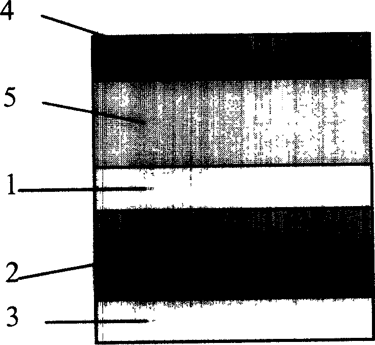
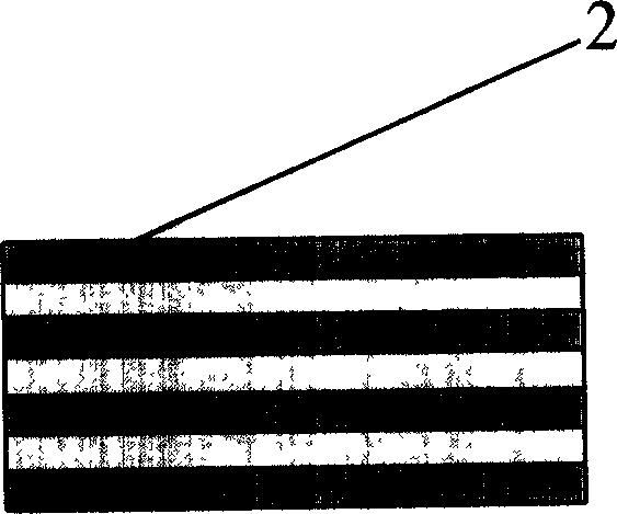
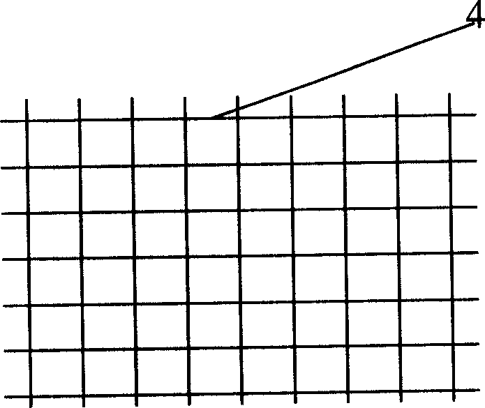
[0012] Such as figure 1 As shown, a microwave oven casing material of the present invention includes a wire mesh, the wire mesh is single or multiple, the wire mesh is connected with a metal-dielectric composite film, and the metal-dielectric composite film The thin film includes a single-layer or multi-layer semiconductor quantum well-like symmetrical structure. Among them, the wire mesh such as figure 1 As shown in 4, it consists of two sets of mutually perpendicular copper wires, the diameter of the copper wires is 0.045 mm, and the distance between any two adjacent parallel copper wires in each set of copper wires is 5 mm. There is no direct conduction between the two sets of copper wires, and they are all fused in the quartz glass. One side of the glass is compounded with a single-layer or multi-layer metal-dielectric multilayer film with a semiconductor quantum well structure, and in this design there is a structure with a 1 / 4 wavelength optical path as described above...


PUM

PropertyMeasurementUnit
Diameteraaaaaaaaaa

Abstract

The invention discloses a microwave oven housing material comprising single layer or multi layer wire mesh screen and single layer or multi layer metallic dielectric composite films of quasi-semiconductor well symmetrical structure. The invention can transparent property in the visible region on one hand, and mask requested microwave in working section or with longer wavelength.

Description

Technical field: [0001] The invention relates to an observation window for electromagnetic wave shielding, in particular to a microwave oven shell material composed of wire mesh and an optical compound film with a symmetrical structure similar to semiconductor quantum wells. Background technique: [0002] In the prior art, the shell of the microwave oven adopts a metal plate. Since the metal plate is opaque, the metal plate on the front of the microwave oven adopts a mesh structure so that the user can observe the food inside. The operating frequency of microwave ovens is generally placed on the resonance frequency of water, that is, around 2450 MHz. In addition, there can be optical frequency microwave ovens that use infrared wave source heating as an auxiliary function. Invention content: [0003] The technical problem to be solved by the present invention is: due to the size of the aperture of the mesh structure in the prior art, the user cannot clearly observe the food...

Claims


Application Information

Patent Timeline
IPC IPC(8): B32B3/24F24C7/02
Inventor 李宏强陈鸿
Owner TONGJI UNIV
Learn More