
Tubular wire rod for double-electrode gas protective welding, its welding method and appts.

A technology of gas shielding and welding methods, applied in the direction of welding medium, welding equipment, welding equipment, etc., can solve the problems of not being able to use only one electrode, complex, large, etc., and achieve the effect of good welding operability and good low temperature toughness

Active Publication Date: 2004-05-26
KOBE STEEL LTD
View PDF6 Cites 1 Cited by
  • Summary
  • Abstract
  • Description
  • Claims
  • Application Information

AI Technical Summary

Problems solved by technology

Thus, for this two-electrode gas shielded welding device, there will be a large and complex problem
In addition, when integrating two electrodes, there is still a problem that only one electrode cannot be used

Method used


Image

  • Tubular wire rod for double-electrode gas protective welding, its welding method and appts.
  • Tubular wire rod for double-electrode gas protective welding, its welding method and appts.
  • Tubular wire rod for double-electrode gas protective welding, its welding method and appts.

Examples


Embodiment 1

[0065] Hereinafter, examples of the present invention will be described in comparison with comparative examples outside the scope of the present invention. Table 4 below shows the types, polarities, and vibration conditions of welding wires used in Examples and Comparative Examples. In addition, the following Table 5 shows the welding workability of each Example and a comparative example. Among them, FCW in Table 4 is a tubular welding wire (Flux Cored Wire), ○ in Table 5 means that it has the same performance as Examples 1-8, ◎ means it is better than Examples 1-8, and △ means it is better than Examples 1-8. Slightly worse, × means poor. In addition, for the test conditions, the shape of the welded plate 1 is 80mm thick, 500mm wide, and 3000mm long, the groove angle is 20°, the groove shape is V-shaped, the groove gap is 4mm on the welding start side, and the welding end is one The side is 8mm. That is, considering the variation of the actual weldment gap, a tapered weld w...

Embodiment 2

[0077] Next, Example 2 of the present invention will be described. In Example 2, first, tubular welding wires having the compositions shown in Table 7 below were produced. Furthermore, in the welding wire composition shown in Table 4, the remainder is Fe, Si, C, etc. In Comparative Example No. 3-21, a conventional tubular welding wire was used.

[0078] 【Table 7】

[0079] Next, using the various welding wires of Examples and Comparative Examples, a double-electrode gas shielded welding method is used to perform vertical welding single pass welding on a plate to be welded with a thickness of 80mm, a width of 500mm, and a length of 1500mm, and evaluate the welding operability and weld metal impact performance. The welding conditions at this time were that the groove shape was V-shaped, the groove weld bead was 8 mm, and the total heat input was about 600 KJ / cm. In addition, the impact test was performed in accordance with the impact test method for welded joints specified in...


PUM


Abstract

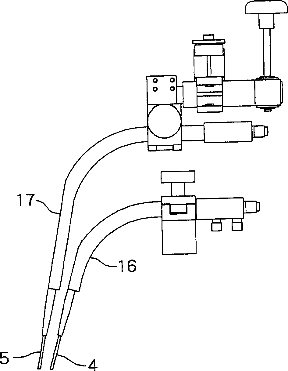
A flux charged wire for two-electrode electro-gas arc welding, a two-electrode electro-gas arc welding method, and a two-electrode electro-gas arc welding device are provided to obtain excellent welding work efficiency and excellent low-temperature toughness. In a two-electrode electro-gas arc welding method, a sliding copper plate(2) sliding upward is put on the surface side of a plate(1) to be welded and a fixed-type backing material is put on the rear side. Two welding wires(4,5) are arranged in a bevel in an isolated state to the surface side and the rear side. The bevel is welded through upright butt welding. The welding wires are flux charged wires. The welding wire of the surface side is vibrated in the plate thickness direction and welding is executed with the polarity of the welding wires reversed. A two-electrode electro-gas arc welding device has a welding trolley supplying the surface-side welding wire in the bevel and moving along the bevel, and a supply member supplying the rear-side welding wire to the position of the backing member side.

Description

technical field [0001] The invention relates to a tubular welding wire for double-electrode gas shielded welding capable of welding one vertical welding bead of thick steel plate, a double-electrode gas shielded welding method and a double-electrode gas shielded welding device. Background technique [0002] As a high-efficiency vertical welding method, gas shielded welding can be used in various fields such as ships, oil storage and irrigation, and bridges, and it has made great contributions to the rationality of welding and the stabilization of joint quality. Especially in the marine field, it is suitable for welding extremely thick plates with a plate thickness of 50 mm or more, such as gunwale strakes and hatch coamings of container ships. [0003] However, in the welding method for this extremely thick plate, in addition to the very low welding speed, the previous single-electrode single-pass welding method is also prone to defects such as poor fusion. In order to elim...

Claims


Application Information

Patent Timeline
IPC IPC(8): B23K9/173B23K35/02B23K35/30B23K35/362
CPCB23K9/121B23K9/16B23K35/368
Inventor 日高武史桥本哲哉长谷薰笹仓秀司中尾哲也
Owner KOBE STEEL LTD
Learn More