Decorative method for forming body
A technology for forming bodies and decorative layers, which can be used in decorative arts, devices for coating liquid on surfaces, special decorative structures, etc., and can solve problems such as environmental impact, natural environment impact, and difficult flow operations
- Summary
- Abstract
- Description
- Claims
- Application Information
AI Technical Summary
Problems solved by technology
Method used
Image
Examples
example 1
[0081] A thermoplastic IMC reagent (pragrass #8000 green) manufactured by Dainippon Paint Co., Ltd. was used as the resin composition. This reagent is a mixture of 100 parts (mass) base reagent and 2 parts (mass) curing agent. The basic reagent consists of 68% (mass) of urethane acrylate (containing cross-linked antioxidants and polymerized antioxidants), 30% (mass) of inorganic components (cobalt oxide) and 2% (mass) of additives (such as Pigment dispersant, internal model release agent, etc.). Described solidifying agent is by the organic peroxide of 50% (mass) (peroxydicarbonate two (4-tert-butyl cyclohexyl ester); the Perkadox 16 that chemical medicine AKZO Co., Ltd. produces) and the plasticizing solvent of 50% (mass) (dibutyl phthalate) composition. The viscosity of this mixture is 5 Pa·s.
[0082] On the other hand, a flat plate forming body 1, which measures 90 mm x 40 mm x 3.0 mm, is molded from ABS resin (manufactured by DAICEL Chemical Industry Co., Ltd.; Cevian ...
example 3
[0099] A resin composition and a molded body 1 similar to those in Example 1 were used.
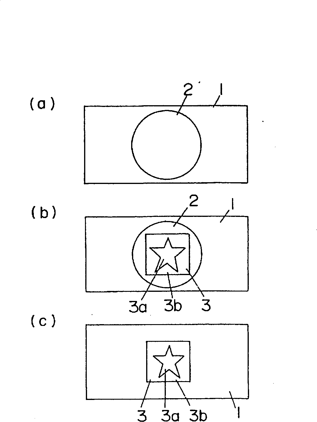
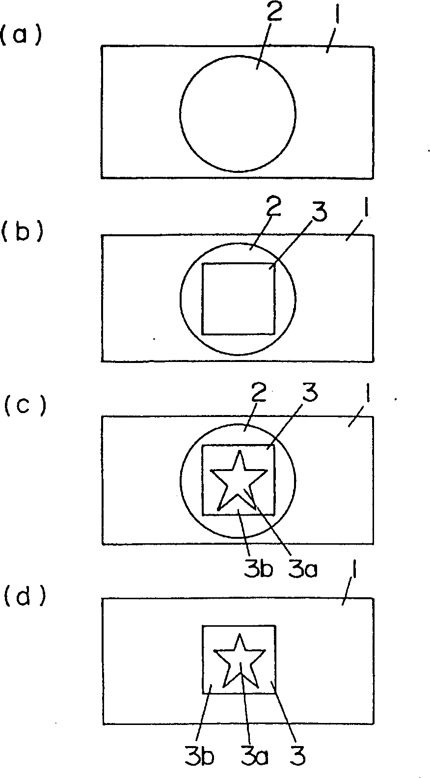
[0100] Such as figure 2 As shown in (a), a resin composition is used to form a circular coating layer 2 in plan view on the surface of a molded body 1 .
[0101] In this coating film layer 2, the entire area of 30 mm x 30 mm was irradiated with a laser beam under the following conditions. Thus, the coating film layer 2 is cured to form a figure 2 (b) The surface decoration layer 3 shown.
[0102] a. Using a semiconductor laser oscillator manufactured by Spectra-Physics, at a wavelength of 795nm, CW (continuous wave) oscillation, output 2.5w, spot diameter Φ1.5mm, scanning speed 2.5mm / sec, and irradiation time 0.6sec Irradiation of a laser beam is carried out.
[0103] Furthermore, in this surface decoration layer 3, further figure 2 The star-shaped area 3a shown in (c) is divided into a plurality of sub-areas, and each divided sub-area is irradiated with a laser beam under the f...
example 4
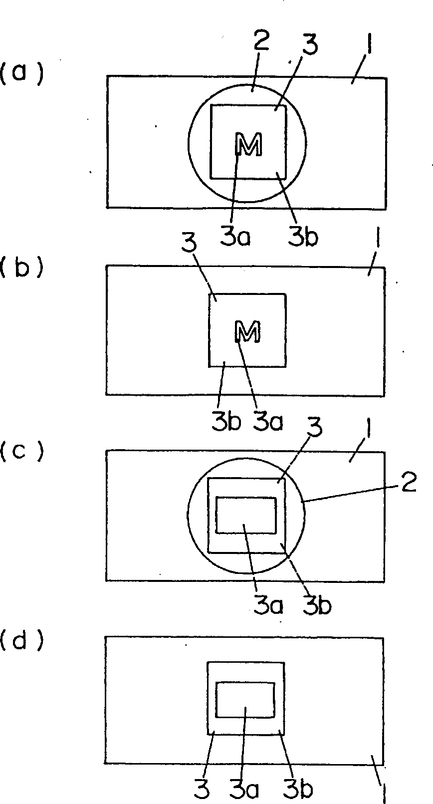
[0113] First, if Figure 6 As shown in (a) and 6(b), in the same manner as Example 1, a first green surface decoration layer 3 measuring 30 mm × 30 mm × 20 μm is formed on the surface of the molded body 1, and the coated film The uncured portion of layer 2 was removed.
[0114] On the other hand, a resin composition having a viscosity of 5 Pa.s was prepared to have a composition similar to that of Example 2 except that iron oxide was used as the pigment. This composition is applied to the first surface decoration layer 3 so as to form the coated film layer 2 having a circular planar figure. The entire area of the coating film layer 2 was irradiated with a laser beam under the following conditions. Thereby coating film layer 2 is solidified, forms the second surface decoration layer 3 that is circular, thick is 20 μm, as Figure 6 (c) and 6(d).
[0115] a. Using a semiconductor laser oscillator manufactured by Spectra-Physics, at a wavelength of 795nm, CW (continuous wave...
PUM
| Property | Measurement | Unit |
|---|---|---|
| thickness | aaaaa | aaaaa |
| tackiness | aaaaa | aaaaa |
| thickness | aaaaa | aaaaa |
Abstract
Description
Claims
Application Information
 - R&D
- Intellectual Property
- Life Sciences
- Materials
- Tech Scout
- Unparalleled Data Quality
- Higher Quality Content
- 60% Fewer Hallucinations
Browse by: Latest US Patents, China's latest patents, Technical Efficacy Thesaurus, Application Domain, Technology Topic, Popular Technical Reports.
© 2025 PatSnap. All rights reserved.Legal|Privacy policy|Modern Slavery Act Transparency Statement|Sitemap|About US| Contact US: help@patsnap.com


