Tantalum containing glasses and glass ceramics
A technology of glass and glass materials, applied in the direction of active dielectric materials, instruments, optical components, etc., can solve the problem of unable to display the gain curve, etc., and achieve the effect of excellent width and flatness characteristics and easy adjustment
- Summary
- Abstract
- Description
- Claims
- Application Information
AI Technical Summary
Problems solved by technology
Method used
Image
Examples
Embodiment 1
[0057] Example 1 -Preparation of KLT glass and glass ceramics
[0058] A variety of KLT glasses and glass-ceramics were prepared by first mixing the batches shown in Table 1 below.
[0059] 88BHH
[0060] 88BHH
[0061] After testing the KLT glass, the glass cake was placed in an electric heating furnace and heated at a temperature of about 650-775° C. for about 0.5-4 hours to ceramize the glass to cause nucleation. After the first soak period, the glass cake is heated at about 750-950°C for about 0.5-4 hours to cause crystal growth. Then, the resulting glass-ceramic was cooled. Table 3 below lists the specific ceramization process for each sample. As shown in Table 3, the appearance and crystalline phase of each glass-ceramic were examined. In addition, Table 3 also shows the dielectric constant, dielectric loss factor and DC resistivity (in terms of Log 10 expressed in ohms-centimeters). For glass ceramic 88BHH, measure the dielectric constant ...
Embodiment 4
[0074] Example 4 -Comparison of emission spectra of glass 88LNQ and glass ceramic 88LNQ
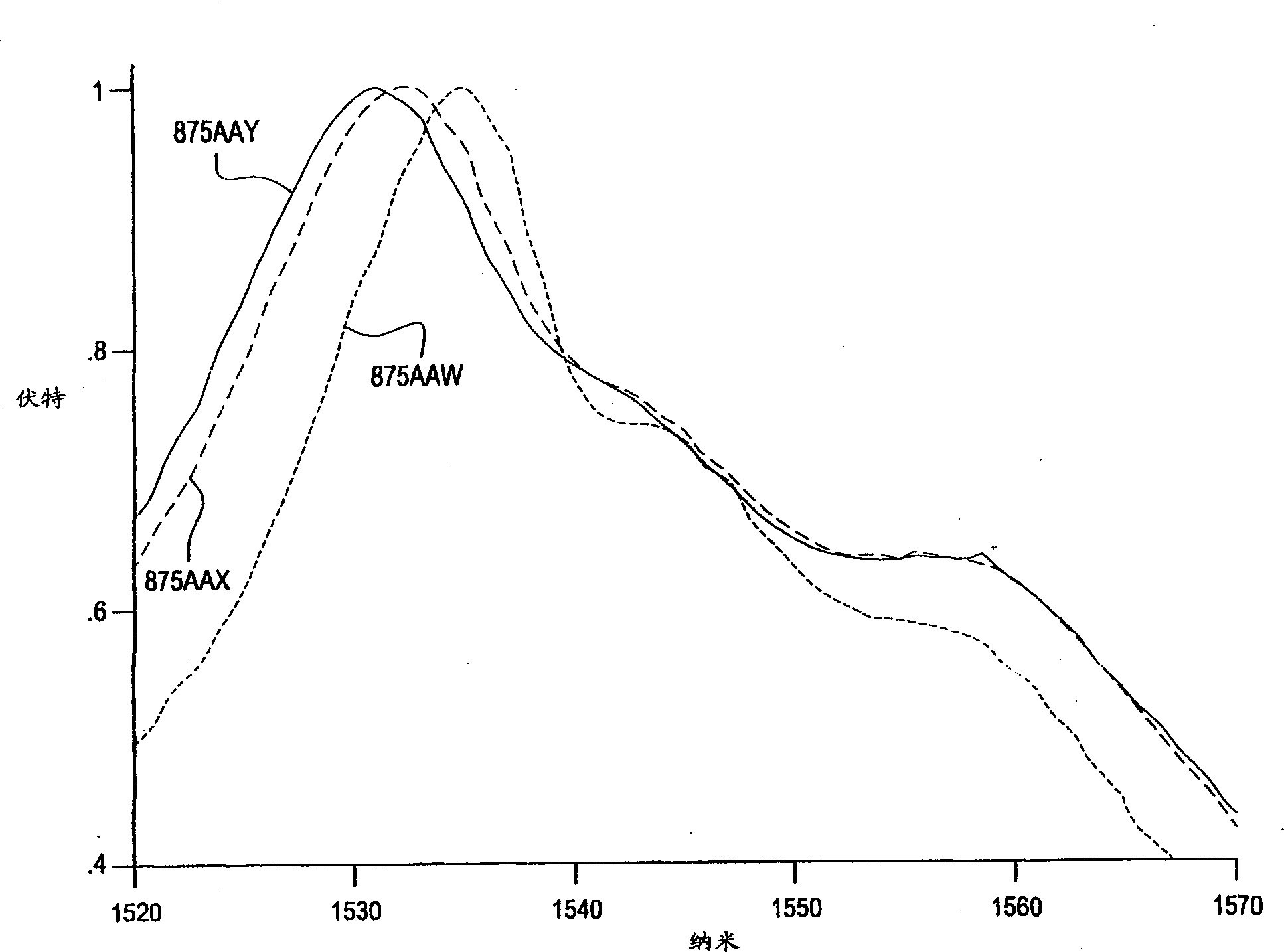
[0075] The common composition of 88LNQ glass and 88LNQ glass ceramics is shown in Table 7, and the emission peaks of their emission spectra are located at or near 1530nm (such as Figure 5 shown). In the band range from 1450nm to 1650nm, the emission spectrum of 88LNQ glass-ceramic is significantly narrower. This shows that Er 3+ The ions are selectively located in the pyrochlore crystalline phase rather than in the glassy phase. Without being bound by a particular theory, it is believed that KTaO 3 Er in the crystal structure 3+ site than Er in glass 3+ The sites are more confined and thus the emission spectrum is narrower.
Embodiment 5
[0076] Example 5 -Preparation of LTN glasses and glass ceramics
[0077] Various LTN glasses and glass-ceramics were prepared by first mixing the batches shown in Table 10 below.
[0078] 875VG
875WH
SiO 2
15.2
14.8
al 2 o 3
5.5
5.4
Ta 2 o 5
64.0
69.8
Nb 2 o 5
9.6
4.7
Li 2 o
5.4
5.3
[0079]Subsequently, the batch was ball milled and loaded into a covered platinum crucible. Put the crucible into an electric heating furnace maintained at about 1300-1650° C., and melt for about 2-16 hours. Next, the melt is poured onto a steel plate to form a cake-shaped melt. The melt was then cooled, and the glass was inspected. Glass 875VG is clear, amber and somewhat opalescent. The glass 875WH is also transparent and has an amber tint.
[0080] After the detection of the LTN glass, the glass cake is placed in an electric heating furnace and heated at a temperat...
PUM
| Property | Measurement | Unit |
|---|---|---|
| crystal size | aaaaa | aaaaa |
| size | aaaaa | aaaaa |
| dielectric loss factor | aaaaa | aaaaa |
Abstract
Description
Claims
Application Information
 - R&D
- Intellectual Property
- Life Sciences
- Materials
- Tech Scout
- Unparalleled Data Quality
- Higher Quality Content
- 60% Fewer Hallucinations
Browse by: Latest US Patents, China's latest patents, Technical Efficacy Thesaurus, Application Domain, Technology Topic, Popular Technical Reports.
© 2025 PatSnap. All rights reserved.Legal|Privacy policy|Modern Slavery Act Transparency Statement|Sitemap|About US| Contact US: help@patsnap.com


