Gel cushion mat

Inactive Publication Date: 2010-09-23
PRODS OF TOMORROW
View PDF23 Cites 75 Cited by
  • Summary
  • Abstract
  • Description
  • Claims
  • Application Information

AI Technical Summary

Benefits of technology

[0012]The layers can be combined or mated in such a way as to have flat-on-flat surfaces, serrated on serrated (such as nested or interlocked), or serrated on flat surfaces. All these combinations will provide varying degrees of support and cushioning effects for the end user. It is also possible to offer different cushioning or support effects on either side thus offering a reversible function for the pad to meet the user's desired support level and comfort. The covers of the mat may also be in different colors and with different textures.
[0015]The edge or lip of the mat may have a corrugated, pleated, creased, crimped or spring type flexible section which will allow the outer most section of the edge or lip to move down and come into contact with and rest on the floor or surface onto which the mat is placed on. The outer section of the edge may have some weight or other means to assist gravity in forcing this section down to make contact and rest flat on the floor. This is particularly useful when the mat is reversible so as to have the leading edge all around the mat touching the floor or surface onto which it is placed to avoid tripping on the mat edge if it is raised or curling of the edges of the mat when stepped on.
[0018]It is an object of the invention to provide an anti-fatigue mat that can be made less expensively than currently available gel-filled anti-fatigue mats.
[0021]It is still another object of the present invention to provide a placemat that is capable of deterring heat transfer.
[0024]It is an object of the invention to provide an anti-fatigue mat that contains a flexible lip that contacts the surface beneath the mat, both to maintain stability and to keep the surface beneath the mat clean.

Problems solved by technology

However, the drawback to using a mat constructed primarily or entirely of gel, is that resilient gel is an expensive material.

Method used


Image

  • Gel cushion mat
  • Gel cushion mat
  • Gel cushion mat

Examples


Embodiment Construction

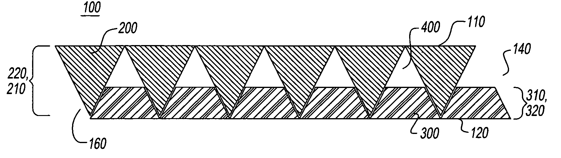
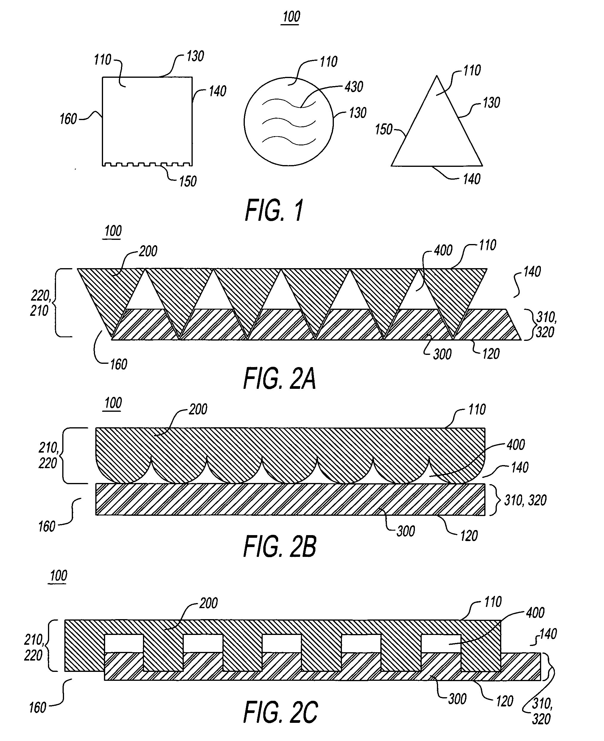
[0031]FIG. 1 is a top view of the invention. FIG. 1 shows pad 100, with pad top 110, pad first side 130, pad second side 140, pad third side 150, pad fourth side 160, and geometric cut out 430.

[0032]FIG. 1 shows three different shapes of the invention, a square, a circle, and a triangle. The invention may be any shape, including but not limited to, trapezoidal, round, square, triangular, rectangular, rectangular with rounded corners, half round, or any design, character shape, animal shape, inanimate object shape, or a logo. The invention may be any color, any number of colors, and / or any combination of colors.

[0033]The pad 100 may be covered with a permanent or removable cover. The cover may be any of the shapes described above; it may be the same shape as the pad 100 or a different shape. The cover may be made of any material, including but not limited to, rubbers, foam rubber, water, fabrics, leather, glass or glass products, sand, animal products, plant products, plastics such a...


PUM

PropertyMeasurementUnit
Thicknessaaaaaaaaaa
Flexibilityaaaaaaaaaa
Shapeaaaaaaaaaa

Abstract

The invention is a pad having a layer of resilient gel disposed on a layer of foam. The gel layer is preferably a silicone gel or other resilient gel such as a thermoplastic elastomer (TPE), SEBS or SEPS and the foam layer is preferably EVA foam. A soft rubber could also be used. The gel layer of the pad may have geometric cutouts such as pleats, grooves, flutings, corrugations, serrated shape, or any combination. The geometric cutouts may have a round, square, trapezoidal, triangular, rectangular, rectangular with rounded corners, half round shape or any combination. The geometric cutouts may also be hollow to further reduce gel material. The shape of the gel layer may be different or independent of the shape of any serrations or geometric cutouts on the foam layer. The pad may be flat or may be formed into a sleeve, a holder for beverage containers, a support pad, or a seat cushions. Many other uses and shapes are conceivable.

Description

CLAIM OF PRIORITY[0001]This application claims priority to U.S. Ser. No. 61 / 210,553 filed Mar. 20, 2009, the contents of which are fully incorporated herein by reference.FIELD OF THE INVENTION[0002]The invention relates to anti-fatigue mats, and in particular floor mats.BACKGROUND OF THE INVENTION[0003]Anti-fatigue floor mats are well known in the art. An anti-fatigue mat is a pad which supports a user while the user is doing a stationary task. The mats are commonly employed in kitchens, workshops, and manufacturing facilities where the user must stand for long periods of time in a stationary position. The cushioning of the anti-fatigue mat reduces stress and tension on the users leg muscles and back, making the user more comfortable during the task performed.[0004]The mats are available in a variety of materials and configurations. In one particular configuration, the mat is made primarily of resilient gel material. The resilient gel material is an excellent material for anti-fatig...

Claims


Application Information

Patent Timeline
IPC IPC(8): A47J41/00B32B3/26B32B3/00B32B5/02B32B1/08A47C20/02
CPCA47C7/021A47C7/282A47C27/14Y10T428/24446A47J36/34Y10T428/24496Y10T428/13A47C27/16Y10T428/249953Y10T442/10
Inventor FERNANDEZ, JUAN
Owner PRODS OF TOMORROW
Why Eureka
Try Eureka