
Optical disc

A technology of optical discs and light reflection films, applied in optical discs, optical recording carriers, optical recording systems, etc., can solve problems such as recording/reproducing failures, achieve reduced jitter values, excellent recording/reproducing characteristics, and wide recording power margins Effect

Inactive Publication Date: 2004-04-28
SONY CORP
View PDF0 Cites 0 Cited by
  • Summary
  • Abstract
  • Description
  • Claims
  • Application Information

AI Technical Summary

Problems solved by technology

[0011] As a result, after this phase-change optical disc is repeatedly recorded many times, it is easy to cause recording / reproduction failure due to fluctuations in recording power and changes in ambient temperature.

Method used


Image

  • Optical disc
  • Optical disc
  • Optical disc

Examples


example 1

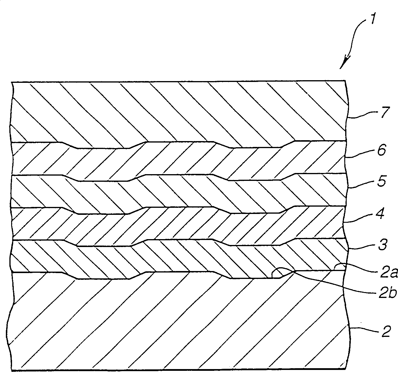
[0074] First, a substrate having a diameter of 120 mm, a thickness of 0.6 mm, and a track pitch of 0.8 µm was prepared.

[0075] Secondly, on this substrate, a 90nm thick ZnS-SiO 2 the first dielectric film.

[0076] Then, use sputtering method on this first dielectric film, use Ge 2 Sb 2 Te 5 target, and a phase-change recording film was formed in an Ar atmosphere.

[0077] Then, a 15nm thick ZnS-SiO film was made by sputtering on the phase change recording film. 2 the second dielectric film.

[0078] Then, on the second dielectric film, an Al 98 Cu 2 target and an Al target to make a light reflective film. This sputtering method is used to obtain Al with a thickness of 15nm and a Cu content of 0.5 atomic percent. 95.5 Cu 0.5 alloy film. Here, the Cu content is controlled by changing the Al 98 Cu 2 target and Al target film formation speed.

[0079] Then, this light reflection film is covered with an ultraviolet curable resin by spin coating, thus obtaining a sin...

example 2

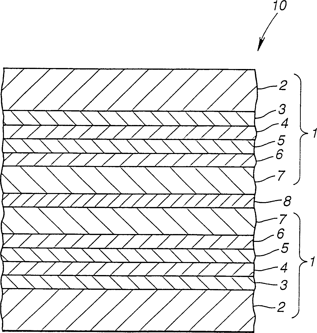
[0100] In addition to changing Al 98 Cu 2 In addition to the film forming speed of the target and the Al target, a light reflective film is produced, and a double-sided phase change optical disc is prepared in the same way as Example 1, so that the thickness of the light reflective film obtained is 15nm, and the composition is that the Cu content is 0.75 atomic percent. Al 99.25 Cu 0.75 alloy.

[0101] Comparative example 2

[0102] In addition to changing Al 98 Cu 2 In addition to the film forming speed of the target and the Al target, a light reflective film is produced, and a double-sided phase change disc is prepared by the same method as in Example 1, so that the thickness of the light reflective film obtained is 15nm, and the composition is that the Cu content is 0.1 atomic percent. Al 99.9 Cu 0.1 alloy.

[0103] Comparative example 3

[0104] In addition to changing Al 98 Cu 2 In addition to the film forming speed of the target and the Al target, a double-si...


PUM

PropertyMeasurementUnit
thicknessaaaaaaaaaa
thicknessaaaaaaaaaa
thicknessaaaaaaaaaa

Abstract

The present invention provides an optical disc capable of effectively reducing a reproduction signal jitter value and obtaining a wider record power margin assuring a reproduction limit jitter value to obtain a preferable recording / reproduction characteristic even after a number of times of recording repeated. The optical disc includes the following films successively formed on a substrate 2: a first dielectric film 3; a phase change recording film 4 whose phase is changed between a crystalline state and an amorphous state thereby to recrod an information signal; a second dielectric film 5; and a light reflection film formed on the phase change recording film 4 and constituted by an Al alloy containing Cu in a range from 0.1 to 1.0 atomic %.

Description

technical field [0001] The present invention relates to an optical disc, which has a recording layer on a substrate, which contains at least a phase change film capable of changing between a crystalline state and an amorphous state, so that the recording layer can be heated with a beam of radiation so that It produces phase changes for recording and erasing information. More specifically, the present invention relates to the improvement of the material constituting the light reflection film on the recording layer. Background technique [0002] As an example of an optical disc that uses a laser beam to record and / or reproduce information signals, an optical disc in which information signals are written in advance with embossed grooves; A phase-change optical disc in which information signals are input; a magneto-optical disc in which information signals are written using the magneto-optical effect of the recording layer. These optical discs have functional films such as a r...

Claims


Application Information

Patent Timeline
Patent Type & Authority Patents(China)
IPC IPC(8): G11B7/2585G11B7/0045G11B7/24047G11B7/24062G11B7/24079G11B7/2433G11B7/258
CPCG11B7/243G11B7/00454Y10S428/913Y10S430/146G11B2007/24314G11B7/258G11B2007/24316G11B7/2585G11B2007/24312Y10T428/21Y10T428/31678G11B7/257G11B2220/2537G11B2007/2431G11B2007/24308
Inventor 斋藤喜浩菊池稔秋原义浩高濑史则
Owner SONY CORP
Learn More