
Efficient flushing pedestal pan

A toilet, high-efficiency technology, applied in the field of sanitary equipment, can solve the problems of insufficient use of instantaneous energy, low water kinetic energy, unsatisfactory flushing effect, etc., and achieves high utilization efficiency, easy flushing control, and ensure the effect of normal use.

Pending Publication Date: 2022-07-22
XIAMEN AXENT
View PDF1 Cites 0 Cited by
  • Summary
  • Abstract
  • Description
  • Claims
  • Application Information

AI Technical Summary

Problems solved by technology

Due to the limited height of the water tank, especially for the intelligent integrated toilet, the water tank is relatively low, the kinetic energy of the water coming out of the water tank is very low, and the flushing effect is not ideal
At the same time, there are also some toilet drain valves on the market that are opened by a hydraulic drive mechanism, but the water used to start the hydraulic drain mechanism only plays the role of opening the drain valve, and the instantaneous energy generated by this part of the water inlet pressure is not fully utilized.

Method used


Image

  • Efficient flushing pedestal pan
  • Efficient flushing pedestal pan
  • Efficient flushing pedestal pan

Examples


Embodiment 1

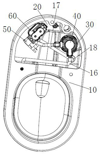
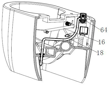
[0051] As shown in the figure, the water tank 20 is further provided with a water pump 50 , and the water pump 50 is used for pumping the water stored in the water tank 20 to supply the hydraulic drive mechanism 40 . Specifically, the water outlet of the water pump 50 is connected to the water inlet 41 through the connecting pipe 17 . That is, in this embodiment, the external pressure water source is to pump the water in the water tank through the water pump 50 . Further, the water tank 20 is also provided with a water inlet valve 60. The water inlet valve 60 has a second outlet 64 and a first outlet 63 for flowing water into the water tank 20. The water outlet from the second outlet 64 is preferably controlled by a solenoid valve. , the water from the first outlet 63 is controlled by a buoy 65 or through an electronically controlled valve, and the water from the second outlet 64 is connected to the outlet of the jet pipe 12, so that the water discharged from the water outlet ...

Embodiment 2

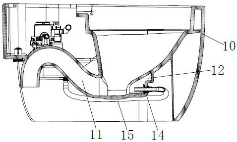
[0054] As shown in the figure, the water tank 20 also includes a water inlet valve 60. The water inlet valve 60 has a second outlet 64 and a first outlet 63 for flowing water into the water tank 20. The water from the first outlet 63 passes through a The buoy 65 is controlled or controlled by an electric control valve, and the water output from the second outlet 64 is controlled by a switch assembly. The second outlet 64 is connected to the water inlet 41 through the connecting pipe 17 . That is, in this embodiment, the external pressure water source is the tap water of the municipal water supply pipe network. In this embodiment, the water outlet 42 is also connected to the outlet of the jetting pipe 12. Specifically, the bottom wall of the water tank is provided with a waterway connecting head, the water outlet 42 is connected to the waterway connecting head through the connecting pipe 18, and the outlet of the jetting pipe 12 A spray connection assembly 14 is installed near...

Embodiment 3

[0057] As shown in the figure, the main difference between this embodiment and the second embodiment is:

[0058] First, the water tank 20 is further provided with a water pump 50 , and the water pump 50 is used to extract the water stored in the water tank 20 to supply the hydraulic drive mechanism 40 . Therefore, the hydraulic drive mechanism 40 has another water inlet besides the water inlet 41, and the water outlet of the water pump 50 is connected to the other water inlet through the connecting pipe 17'. That is, in this embodiment, the external pressure water source can be either the water in the water tank pumped through the water pump 50 or the tap water from the municipal water supply pipe network. Therefore, a first check valve 90 is arranged between the second outlet 64 and the water inlet 41, and a second check valve 90' ​​is arranged between the water outlet of the water pump 50 and the other water inlet, so that the The water flowing into the hydraulic chamber 4...


PUM


Abstract

The invention discloses an efficient flushing pedestal pan which comprises a pedestal pan body and a water tank, the pedestal pan body is provided with a blow-off pipeline, an injection pipeline and a brushing pipeline, a drain valve is arranged in the water tank, and a drain outlet of the drain valve is communicated with the injection pipeline, and the efficient flushing pedestal pan is characterized by further comprising a hydraulic driving mechanism which is connected to the drain valve and can drive the drain valve to drain water; the hydraulic driving mechanism is provided with a hydraulic cavity, a water inlet and a water outlet, the water inlet and the water outlet can be communicated with the hydraulic cavity, the water inlet is connected with an external pressure water source, and the water outlet is communicated to the scrubbing pipeline inlet so that the external pressure water source can flow into the water inlet. And an external pressure water source flows out from the water outlet and is sprayed out from the scrubbing pipeline to flush the peripheral wall of the toilet bowl body. The external pressure water source is used for supplying water to the scrubbing pipeline after the drain valve is opened, the utilization efficiency of the water source is extremely high, and meanwhile flushing control is easy and convenient.

Description

technical field [0001] The present application relates to sanitary equipment, in particular to an efficient flushing toilet. Background technique [0002] The current toilet is generally provided with two water outlet pipes, namely the jet pipe and the brush ring pipe. The water flow is divided into two parts after flowing out from the drain valve of the water tank, one part of the water flows through the brush ring pipe to wash the inner ring surface of the toilet body, and the other part of the water flows out through the jet pipe to spray and wash the bottom of the toilet body. Since the water from the two water outlet pipes comes to the drain valve, and the water level of the brush ring pipe is relatively high, it is difficult to effectively guarantee the water volume. Due to the limited height of the water tank, especially for the intelligent integrated toilet, the water tank is relatively low, the kinetic energy of the water coming out of the water tank is very low, a...

Claims


Application Information

Patent Timeline
IPC IPC(8): E03D5/01E03D1/38E03D5/09E03D5/10
CPCE03D5/01E03D1/38E03D5/09E03D5/10
Inventor 江长发李惜平陈金吴建福
Owner XIAMEN AXENT
Learn More