
Offshore wind power concrete floating foundation structure crack monitoring system and method

A basic structure, offshore wind power technology, applied in the direction of basic structure engineering, basic structure testing, measuring devices, etc., can solve problems such as interference with anti-corrosion coating adhesion, rust monitoring system, accelerated corrosion of basic structures, etc., to achieve excellent resistance to seawater erosion Performance, the overall system is simple and efficient, and the effect of stable chemical properties

Pending Publication Date: 2022-07-15
CHINA HYDROELECTRIC ENGINEERING CONSULTING GROUP CHENGDU RESEARCH HYDROELECTRIC INVESTIGATION DESIGN AND INSTITUTE
View PDF0 Cites 0 Cited by
  • Summary
  • Abstract
  • Description
  • Claims
  • Application Information

AI Technical Summary

Problems solved by technology

[0003] However, the damage monitoring schemes for concrete structures in the prior art cannot be applied to the marine environment. For example, the "Structural Damage Monitoring System and Method Based on Piezoelectric Ultrasonic-Smart Grid" proposed by Zhang Benniu et al. The sensitive wires used are metal wires, which are prone to corrosion in the marine environment and cause the monitoring system to fail, and the monitoring system contains complex control circuits. Adhesion to the concrete surface causes the anti-corrosion coating to fall off easily and accelerates the corrosion of the foundation structure

Method used


Image

  • Offshore wind power concrete floating foundation structure crack monitoring system and method
  • Offshore wind power concrete floating foundation structure crack monitoring system and method
  • Offshore wind power concrete floating foundation structure crack monitoring system and method

Examples


Embodiment

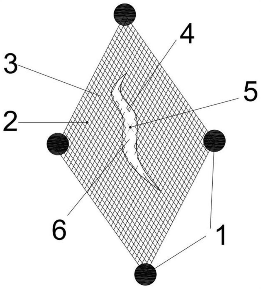
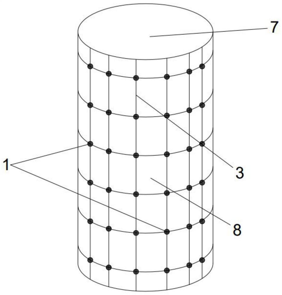
[0030] In the specific implementation, an array of photoelectric signal transceivers is installed on the surface of the concrete base structure 7, and a positioning grid 8 is established. 1, in which four photoelectric signal transceivers are positioned on a grid 8, that is, one photoelectric signal transceiver is set on the corner of each positioning grid 8, such as figure 2 shown.

[0031] The photoelectric signal transceiver 1 includes an optical signal transmitting unit, an optical signal receiving unit, a photoelectric signal converting unit and a radio signal transmitting unit; the optical signal transmitting unit and the optical signal receiving unit are all connected to the photoelectric signal converting unit, and the The photoelectric signal conversion unit is connected to the radio signal transmitting unit; the photoelectric signal transceiver communicates with the main control machine through the radio signal transmitting unit.

[0032] An optical fiber network 3...


PUM


Abstract

The invention relates to the field of concrete structure crack monitoring, and discloses an offshore wind power concrete floating foundation structure crack monitoring system and a corresponding monitoring method which are suitable for the marine environment and can be well matched with an anti-corrosion coating. The monitoring system comprises a main control computer, a photoelectric signal transceiver array and an optical fiber network, wherein the photoelectric signal transceiver array and the optical fiber network are positioned below an anti-corrosion coating and are adhered to a concrete floating foundation structure; the photoelectric signal transceiver array comprises photoelectric signal transceivers which are combined and arranged on the surface of the concrete floating foundation structure according to a certain position; the optical fiber network is connected with photoelectric signal transceivers, and each photoelectric signal transceiver communicates with the main control computer.

Description

technical field [0001] The invention relates to the field of crack monitoring of concrete structures, in particular to a system and method for monitoring cracks of an offshore wind power concrete floating foundation structure. Background technique [0002] The concrete structure in the marine environment will be corroded by chloride ions, magnesium ions and sulfate ions in seawater. These harmful ions will enter the concrete through the concrete pores, and will interact with the calcium hydroxide and calcium aluminate hydrate in the concrete. The resulting insoluble salts tend to have large volume expansion, resulting in a large internal stress inside the concrete pores, and long-term accumulation causes cracks in the concrete. In addition, the chloride ions in seawater will also penetrate into the concrete through the cracks in the concrete, causing the surface of the steel bars in the concrete to corrode, thus seriously affecting the durability of the structure, and at the...

Claims


Application Information

Patent Timeline
Patent Type & Authority Applications(China)
IPC IPC(8): G01B11/02G01B11/14G01B11/24G01N21/95E02D33/00E02D27/42E02D31/06
CPCG01B11/02G01B11/14G01B11/24G01N21/95E02D33/00E02D27/425E02D31/06
Inventor 刘欣怡胡中波李阔刚傲
Owner CHINA HYDROELECTRIC ENGINEERING CONSULTING GROUP CHENGDU RESEARCH HYDROELECTRIC INVESTIGATION DESIGN AND INSTITUTE
Learn More