
Process and equipment for recycling nitrogen trifluoride electrolytic residue resources

A nitrogen trifluoride and resource recovery technology, applied in the direction of improving process efficiency, calcium/strontium/barium fluoride, ammonium halide, etc., can solve the problems of high energy consumption, waste of resources, complicated treatment methods, etc.

Pending Publication Date: 2022-07-08
河南众信蓝天环保装备有限公司
View PDF0 Cites 0 Cited by
  • Summary
  • Abstract
  • Description
  • Claims
  • Application Information

AI Technical Summary

Problems solved by technology

The treatment methods for the electrolytic waste residue of nitrogen trifluoride mainly include the following methods: one is to carry out lime neutralization and precipitation on the fluoride ions in the nickel-containing waste residue, and then use a chemical method to treat the ammonium ion with ammonia nitrogen. The method is only to carry out harmless treatment, without realizing the recycling of resources, resulting in waste of resources, and will increase the cost of treatment; the other is to dissolve the electrolytic nickel-containing waste residue in water, and then separate the solid and liquid to make the liquid become Ammonium fluoride aqueous solution, the solid becomes nickel-containing waste residue, and the solid residue needs to be further separated. This treatment method is relatively complicated, and the separated nickel-containing waste residue is hazardous waste, which still needs to be handled by a professional company.
Another method is to use hydrofluoric acid to dissolve nickel slag, add sulfuric acid to the electrolyte, and use electrolysis to recover nickel metal. This treatment method consumes a lot of energy, and after adding sulfuric acid, other impurities will be introduced, resulting in subsequent treatment processes and cost increase

Method used


Image

  • Process and equipment for recycling nitrogen trifluoride electrolytic residue resources
  • Process and equipment for recycling nitrogen trifluoride electrolytic residue resources
  • Process and equipment for recycling nitrogen trifluoride electrolytic residue resources

Examples


Embodiment 1

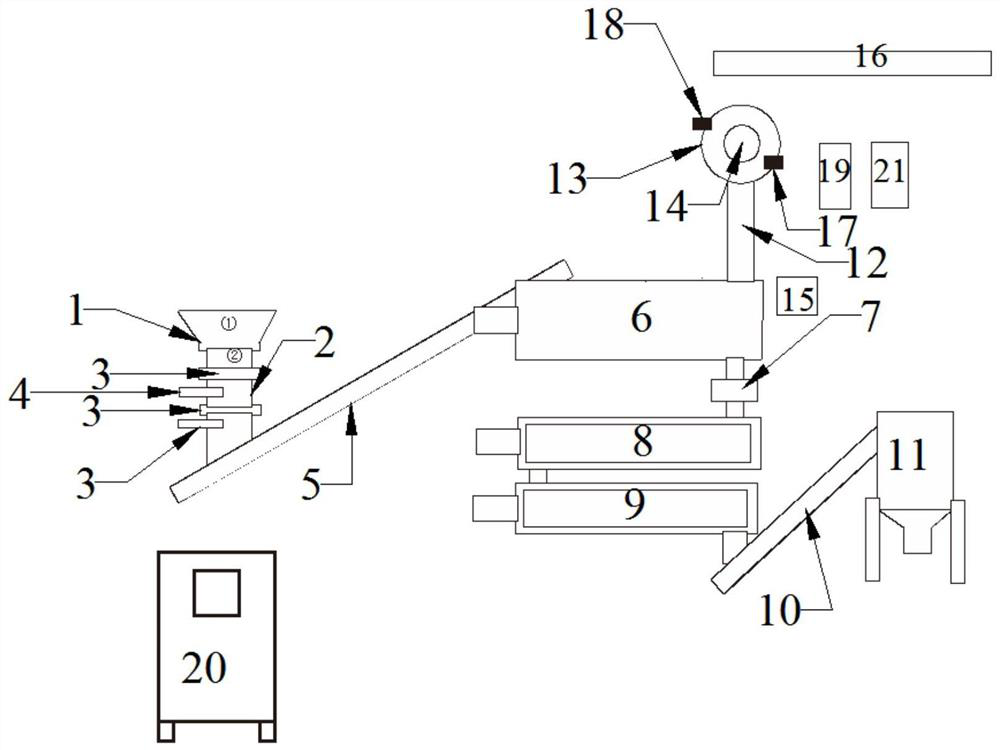
[0036] A device for recycling nitrogen trifluoride electrolysis residue resources, such as figure 1 As shown, the use method of the equipment is as the above-mentioned process of nitrogen trifluoride electrolysis residue resource recovery. The calcium oxide tank 16, the steam defluorination device 8, the ammonia water tank, the heat exchange device 21 and the cooling device 9; the above-mentioned devices are all controlled and operated by the control cabinet 20;

[0037] The outlet of the crushing device is connected with the inlet of the feeding device, the outlet of the feeding device is connected with the inlet of the high-temperature anaerobic pyrolysis device 6, and the gas outlet of the high-temperature anaerobic pyrolysis device 6 is cracked through the The gas pipe 12 is connected to the air inlet of the condensing device 14, the condensing liquid outlet 18 of the condensing device 14 is connected to the condensing liquid inlet 17 of the crystallization device 13 throu...

Embodiment 2

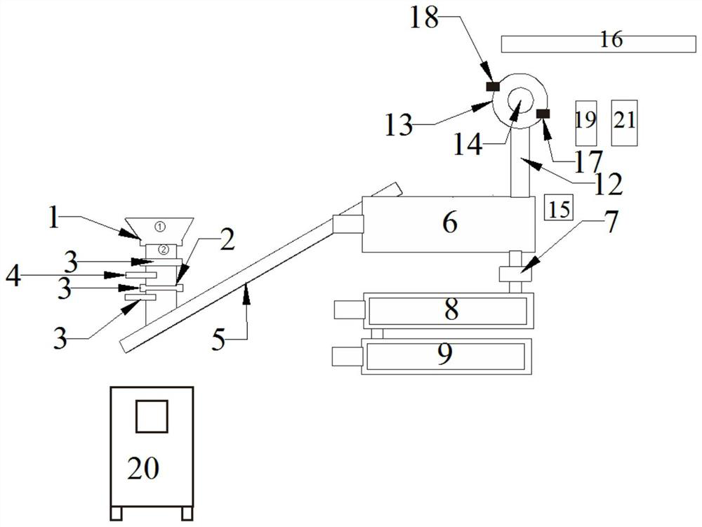
[0046] A device for recycling nitrogen trifluoride electrolysis residue resources, such as figure 2 As shown, the use method of the equipment is as the above-mentioned process of nitrogen trifluoride electrolysis residue resource recovery. The calcium oxide tank 16, the steam defluorination device 8, the ammonia water tank, the cooling device 9, the heat exchange device 21 and the discharging device; the above-mentioned devices are all controlled and operated by the control cabinet 20;

[0047] The outlet of the crushing device is connected with the inlet of the feeding device, the outlet of the feeding device is connected with the inlet of the high-temperature anaerobic pyrolysis device 6, and the gas outlet of the high-temperature anaerobic pyrolysis device 6 is cracked through the The gas pipe 12 is connected to the air inlet of the condensing device 14, the condensing liquid outlet 18 of the condensing device 14 is connected to the condensing liquid inlet 17 of the crysta...

Embodiment 3

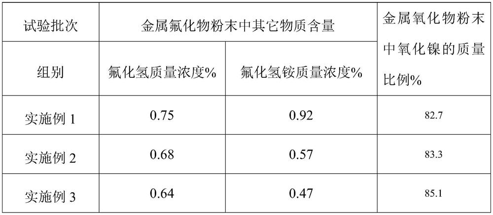
[0057] The device of Example 3 is the same as that of Example 2, and the specific process is different.

[0058] The process of the nitrogen trifluoride electrolysis residue resource recovery of the present embodiment comprises the following steps:

[0059] 1) The nitrogen trifluoride electrolysis residue is pulverized by a shredder, and pulverized to particles below 20 mm;

[0060] 2) The pulverized residue is sent to the high-temperature anaerobic pyrolysis device 6 through the feeding device, and high-temperature anaerobic pyrolysis is carried out at 600 ° C to obtain the gas and powder after the pyrolysis; wherein, the powder is metal fluoride powder, The condensation and crystallization adopts water cooling, and the water cooling is normal temperature tap water, and the tap water is cooled by an air-cooled heat exchanger to realize recycling;

[0061] 3) the gas after the pyrolysis is added to the condensing device 14, condensed to obtain condensed liquid and non-condens...


PUM

PropertyMeasurementUnit
boiling pointaaaaaaaaaa
melting pointaaaaaaaaaa

Abstract

The invention discloses a nitrogen trifluoride electrolytic residue resource recovery process and equipment, and the process comprises the following steps: crushing electrolytic residues, carrying out high-temperature anaerobic pyrolysis, retaining metal fluoride in a powder form, gasifying most of ammonium bifluoride and hydrogen fluoride into steam, introducing the pyrolyzed steam into a condensing device, and condensing the condensed steam to obtain the nitrogen trifluoride electrolytic residue resource. The condensate after condensation is ammonium bifluoride, the non-condensable gas is hydrogen fluoride, crystallizing the condensate, and recovering to obtain an ammonium bifluoride solid; introducing the hydrogen fluoride noncondensable gas into a container filled with calcium oxide for reaction to generate calcium fluoride; metal fluoride residues obtained after pyrolysis are completely defluorinated through high-temperature steam, the defluorinated steam is absorbed by ammonia water, and metal oxide powder obtained after defluorination is cooled and then recycled. Separation and clean production of ammonium bifluoride, hydrogen fluoride and metal oxides in the nitrogen trifluoride electrolytic residues are realized by utilizing phase change characteristics of gas, solid and liquid of ammonium bifluoride, hydrogen fluoride and metal fluoride at different temperatures and combining with equipment, and resources are recycled.

Description

technical field [0001] The invention relates to the technical field of recycling nitrogen trifluoride electrolysis residues, in particular to a process and equipment for recycling nitrogen trifluoride electrolysis residue resources. Background technique [0002] As an excellent plasma etching gas in the microelectronics industry, high-purity nitrogen trifluoride gas has excellent etching rate and selectivity for silicon and silicon oxide, so it occupies an important position in many industries such as integrated circuits and chip manufacturing. In the industry, there are two production methods of nitrogen trifluoride: one is the electrolysis of anhydrous hydrogen fluoride to generate fluorine gas, which is then reacted with molten ammonium bifluoride to generate nitrogen trifluoride; the other is the electrolysis of anhydrous hydrogen fluoride and molten ammonium bifluoride. The mixture can generate nitrogen trifluoride directly in the electrolytic cell. The nitrogen triflu...

Claims


Application Information

Patent Timeline
Patent Type & Authority Applications(China)
IPC IPC(8): C01C1/16C01F11/22C01G53/04
CPCC01C1/162C01F11/22C01G53/04C01P2006/80Y02P10/20
Inventor 王国东王金淼刘春姣张中财杨武佂王朋玉王林玉
Owner 河南众信蓝天环保装备有限公司
Learn More