Flue gas denitration utilization device for waste heat boiler of gas turbine

A waste heat boiler and flue gas technology, applied in the field of flue gas denitrification, can solve the problems of high hardware investment cost, high maintenance work and cost, and achieve the effects of saving operating costs, ensuring stable progress, and ensuring stable preparation

Pending Publication Date: 2022-06-24
HUANENG NANTONG GAS TURBINE POWER GENERATION CO LTD
View PDF6 Cites 1 Cited by
  • Summary
  • Abstract
  • Description
  • Claims
  • Application Information

AI Technical Summary

Problems solved by technology

[0003] However, in order to ensure that the ammonia gas produced by the hydrolysis of urea does not undergo a reverse reaction, the transportation of ammonia gas must be carried out in an environment not lower than 175°C. The high-temperature flue gas transported by the high-temperature fan heats the cold dilution air, or uses a steam heat exchanger to exchange heat with the cold dilution air. The hardware investment cost is high, and the later maintenance work and cost are also relatively high.

Method used


Image

  • Flue gas denitration utilization device for waste heat boiler of gas turbine
  • Flue gas denitration utilization device for waste heat boiler of gas turbine
  • Flue gas denitration utilization device for waste heat boiler of gas turbine

Examples


Embodiment Construction

[0028] The technical solutions in the embodiments of the present invention will be clearly and completely described below with reference to the accompanying drawings in the embodiments of the present invention. Obviously, the described embodiments are only a part of the embodiments of the present invention, but not all of the embodiments.

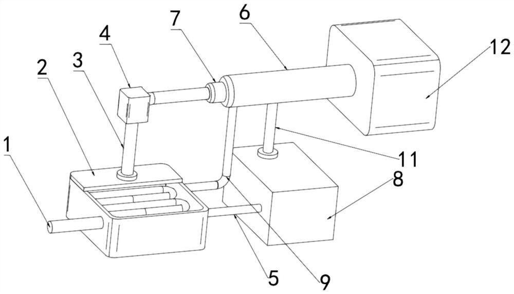
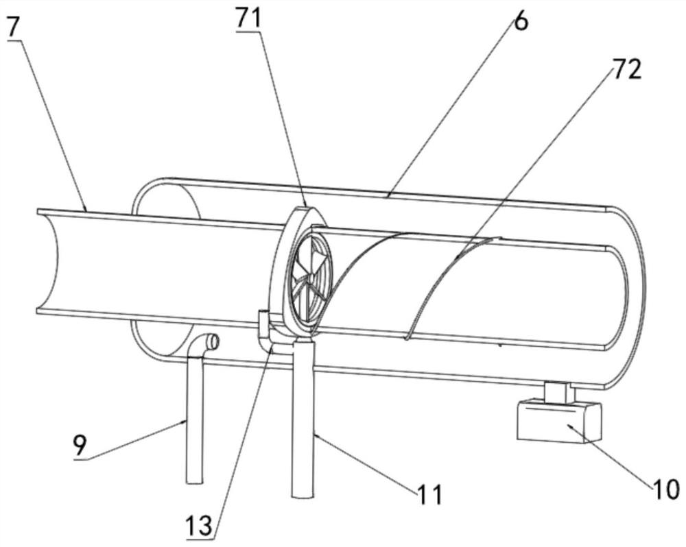
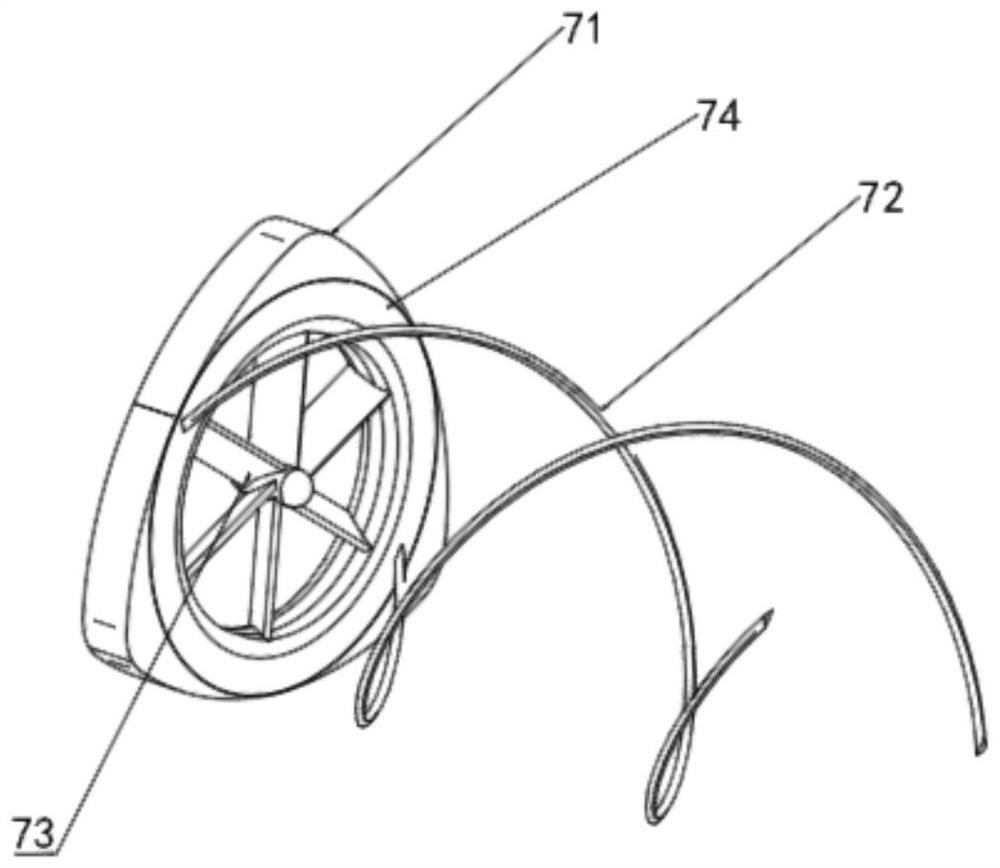
[0029] refer to Figure 1-7 , a flue gas denitration utilization device of a gas turbine waste heat boiler, comprising a heat exchanger 2, a urea hydrolysis device 8 and a denitration reactor 12, the air inlet of the heat exchanger 2 is connected with a flue gas intake pipe 1, and the The output port is connected with a decompression and desuperheating flue gas pipe 3, the other end of the decompression and desuperheating flue gas pipe 3 is provided with a pneumatic regulating valve 4, and the output end of the pneumatic regulating valve 4 is connected with a dilution air duct 7. The other end is connected with the ammonia gas input end of ...


PUM


Abstract

The invention discloses a gas turbine waste heat boiler flue gas denitration utilization device, and relates to the field of flue gas denitration, the gas turbine waste heat boiler flue gas denitration utilization device comprises a heat exchanger, a urea hydrolysis device and a denitration reactor, a gas inlet of the heat exchanger is connected with a flue gas inlet pipe, and an output port of the heat exchanger is connected with a pressure reduction and temperature reduction flue gas pipe; a pneumatic control valve is arranged at the other end of the pressure and temperature reduction flue gas pipe, the output end of the pneumatic control valve is connected with a dilution air pipeline, the other end of the dilution air pipeline is connected with the ammonia gas input end of the denitration reactor, and a heat tracing pipeline is fixedly installed on the side face of the denitration reactor; the heat tracing pipeline is located on the outer side of the dilution air pipeline. The flue gas of the unit is directly extracted, so that the laying and operation cost of a high-temperature fan and a steam heat exchanger can be saved, the transportation condition of an ammonia gas mixture after hydrolysis is met, the operation cost is effectively reduced, and efficient and stable denitration work is ensured.

Description

technical field [0001] The invention relates to the technical field of flue gas denitration, in particular to a flue gas denitration utilization device of a gas turbine waste heat boiler. Background technique [0002] Nitrogen oxide in flue gas is one of the important pollution sources of the atmosphere, and its pollution is very harmful. The research on flue gas denitrification technology is listed as the focus of air pollution prevention and control in many countries. At present, urea, ammonia water and liquid ammonia are used for catalytic reduction in denitrification. Denitrification, the urea solution is heated and hydrolyzed by high temperature steam in the hydrolyzer to generate ammonia gas, and then the ammonia gas is mixed with the dilution air and then sprayed into the denitration reactor. Under the action of the catalyst, the ammonia reacts with the nitrogen oxides in the flue gas , so as to achieve the effect of removing NOx. [0003] However, in order to ensure...

Claims


Application Information

Patent Timeline
Patent Type & Authority Applications(China)
IPC IPC(8): B01D53/86B01J19/18B01D53/56F23J15/02F23J15/06F26B5/14B08B9/023B08B1/00C01C1/08
CPCB01D53/8631B01D53/8625B01J19/0053B01J19/0066B01J19/18F23J15/02F23J15/06F26B5/14B08B9/023B08B1/00C01C1/086B01D2251/2062
Inventor 王剑栋陈兵王宝琦谢伟华蒋俊荣陆启芹
Owner HUANENG NANTONG GAS TURBINE POWER GENERATION CO LTD
Why Eureka
Try Eureka